
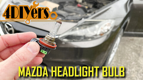
How to Replace the Low Beam Headlight Bulbs on a Mazda CX9
How to replace the low beam bulbs on your Mazda CX9. This is a 2015 model which is the face-lifted version of the first generation. #mazda #mazdacx9 #ledlights
Website: http://4diyers.com
Patreon: https://www.patreon.com/4diyers
Facebook: https://www.facebook.com/4diyers
Twitter: https://twitter.com/4DIYers
Instagram: https://www.instagram.com/4diyers/
Tumblr: http://4diyers.tumblr.com
Pintrest: https://www.pinterest.com/4diyers/
Tools/Supplies Needed:
-10mm socket
-3/8" drive ratchet
-3" extension
Procedure:
First is opening the hood to gain access to the rear of the headlights.
Just to give you a view behind those headlights, there is a done cap that needs to be removed to gain access to the bulb inside.
There will be plastic tabs around the perimeter of the domed cap, grab onto these and twist counterclockwise, then remove.
It was hard for me to get a camera in here without my hand being in the way. As you can see there is the bulb and wire connector.
You can unclip the connector first or after one the bulb is out, whatever is easier for you. For me, I pulled out the tang on the electrical connector and then pushed it off the light.
I then rotated the bulb counterclockwise, and pull out the bulb from the assembly.
I’m replacing the factory bulbs with LEDs to improve the extremely dim light output. Here is a comparison between the bulbs, here you can see the three tabs around the perimeter, two are the same size while one is larger.
The new bulb is then inserted into the light, I’m using LEDs so it’s a little harder to match the reference position of the bulb alignment tabs. You’ll feel it lock into place, push it in, then rotate clockwise until it stops.
After that is plugging in the electrical connector.
Finally is installing the protective cap. Rotate until you can feel those alignment tabs lock into place, then rotate clockwise until it stops.
Moving onto the passenger side requires an extra step. The coolant reservoir tank will need to be removed.
Using a 3/8 drive ratchet with a 3 inch extension and a 10 mm socket, remove the three bolts on the coolant reservoir.
Once those bolts have been removed, then you can push the reservoir back towards the windshield, do not disconnect the lines.
Again the same process as the driver side, remove the domed, cover by rotating counterclockwise. Then to access the bulb, again unclipped the connector and rotate the bulb counterclockwise then pull it straight out.
Finally install the new bulb replacement, then plug in the electrical connector. If you are using an LED bulb, you will need to Work by field in finding out if those alignment tabs are properly in place. Always give the bulb a pull back to make sure it is locked in place.
Then fasten down the coolant reservoir. Install those 3 10mm bolts and tighten. Do not over-tighten as this is only plastic.
After that is testing, the headlights to ensure they are working correctly and you are officially done.
Thank you to all those who watch my videos and support my content. Don't forget to subscribe to my channel for future tutorial videos and like my video if you found it helpful. New videos are always being uploaded every week!
© 4DIYers 2013
All Rights Reserved
No part of this video or any of its contents may be reproduced, copied, modified or adapted, without the prior written consent of the author.
21
views
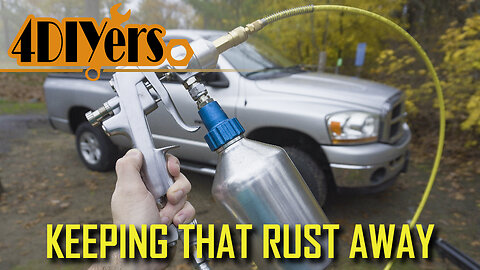
How to Protect your Vehicle from Rust - 2nd Year Follow-up
Due to this being a popular request over the last year from my first rustproofing video using the wax and oil hybrid spray, here you’ll get to see my follow-up spray for this year. In this video I will be showing you how to apply a second application for the rust inhibiting coating on my Dodge Ram and you can see how that original application is holding up too. If you’re living in a climate that experiences snowy winters and has salt applied to the roads, this is by far the best method is protecting your vehicle. This time around I’m using only an oil-based coating. #dodgeram #rustproofing #canada
Website: http://4diyers.com
Patreon: https://www.patreon.com/4diyers
Facebook: https://www.facebook.com/4diyers
Twitter: https://twitter.com/4DIYers
Instagram: https://www.instagram.com/4diyers/
Tumblr: http://4diyers.tumblr.com
Pintrest: https://www.pinterest.com/4diyers/
Tools/Supplies Needed:
-oil based coating
-rustproofing applicator gun
-rubber gloves
-safety glasses
-respirator
Chapters:
00:00 Intro
00:30 Coating Type & Applicator Gun
02:16 Spaying Inside the Frame
03:33 Inside the Rockers
04:28 Behind the Rear Fenders
04:44 Driver's Side
05:01 Inside the Rockers
05:33 Inside the Doors
06:22 Inside the Tailgate
06:42 Under the Hood
07:11 The Full Underbody
Procedure:
I’m doing this on a cooler day but it’s typically recommended to apply this in warmer weather as it’ll creep better on the surface, getting into all those cracks and crevices. I’m using the same applicator gun as last year, it has a pressurized tank and comes with different attachments to get in behind body panels, inside the frame, work around tight areas and even a fan spray for large areas. Each product will have it’s own instructions. Ensure it’s mixed, so shake up the container. For the Dodge Ram, I used the whole can which is 3.78L or 1 US gallon. Fill up the container, not to the top as we need to make room for the pick-up tube so this can displace some of the coating.
Install the container and tighten. Then place the container in a bucket of hot water. This will overcome the cooler weather, today was the minimum required temperature for applying this product. Allow it to soak for about 10 minutes. I’m using the same small pancake compressor. I set the regulator to around 75 psi but bumped it up after to about 85 psi due to the cooler weather. Do not exceed the maximum pressure of the applicator gun.
With this having a full boxed frame, I’ll start with the inside of the frame, front first and work my way back to the rear of the truck. The wand I’m using here has a 360 degree spray to provide an even coating inside enclosed areas. Find any factory-made holes inside the frame, push the wand fully inside, press the trigger to dispense the spray and slowly pull the wand out. Feed rates will depend on how much product is being applied along with air pressure.
Now is the outer cavity of the rockers. Someone had predrilled access holes in the rockers as shown by the black caps and this can be done to your vehicle too. A step drill is recommended for such a job as they make a clean hole in body panels and you can purchase caps to plug up the holes afterward. Here is a great example of using the same hole to work ahead and behind it making sure the inside is fully coated. Once done, then reinstall the cap.
Next step is the doors. These have been pre-drilled but the drains behind the gasket are big enough to slide the cavity hose in. The spray should be directed at the bottom of the door and partly up the sides, just where the water may drain inside. Drains may vary between vehicles, typically there’s one at the front and rear. On this Dodge, they’re hidden behind the door seal.
Moving onto the rear of the vehicle, for this truck it would be the tailgate. On other vehicles this maybe a truck or hatch. The 360 degree spray nozzle is used here too and a mist is sprayed throughout the inside.
Under the hood, spray within any structure members or tube cavities, in the fender cavity between the inner and outer fenders, radiator support, steel structure behind the bumper, within the hood structure, etc.
For the last step, this is the full outer coating on the underside of the vehicle. There are a couple different attachments that can be used such as the spray tip and the 90 degree wand tip which is what I prefer. The spray tip would be better if you have your vehicle elevated. The 90 degree tip allows me to get into tight areas, around corners, and even provides a great overall surface mist.
Thank you to all those who watch my videos and support my content. Don't forget to subscribe to my channel for future tutorial videos and like my video if you found it helpful. New videos are always being uploaded every week!
© 4DIYers 2013
All Rights Reserved
No part of this video or any of its contents may be reproduced, copied, modified or adapted, without the prior written consent of the author.
36
views
1
comment
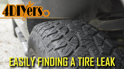
How to Easily Find a Tire Leak At Home Method
How to find a tire leak. There are a few different areas where a tire can leak, the tire can take about a week or two to deflate or it may even happen overnight. The position of the wheel in reference to the leak can even affect the speed of a leak. For this I’m using the Toyota Tacoma as an example. At first the tire would require a top-up every couple of months and up until recently, it would leak down in a week or two depending on the location of the leak in reference to the ground. This may flex the tire one way or another, either opening or closing up that leak. #wheelrepair #tirerepair
#OEMTOOLS Pliers Set: https://www.mobiledistributorsupply.com/22645-oemtools-22645-4-piece-automotive-pliers-set-oem
Website: http://4diyers.com
Patreon: https://www.patreon.com/4diyers
Facebook: https://www.facebook.com/4diyers
Twitter: https://twitter.com/4DIYers
Instagram: https://www.instagram.com/4diyers/
Tumblr: http://4diyers.tumblr.com
Pintrest: https://www.pinterest.com/4diyers/
Tools/Supplies Needed:
-wheel wrench
-jack
-spray bottle with soap and water
-air compressor
Procedure:
First the wheel will need to be removed from the vehicle. Next was pumping up the tire. The generic pressure is 32psi, however you can bump it up to about 35-36psi to help increase that leak so it’s more noticeable. When putting a higher pressure in your tires, also refer to the tire’s info so you’re not exceeding the maximum rated pressure.
Using a spray bottle with a mixture of water and dish soap, apply it to the tire and even the wheel. There have been instances in the past, notably with steel wheels where they were poorly made and developed leaks over time. Possible causes of a leak can include a faulty or failing wheel, valve stem either around where it seats in the wheel or the valve core, checking or cracks in a tire where it’s deteriorating, around where the bead of the tire seats against the wheel, or damage which includes a puncture or cut.
Flip over the wheel and again spray it down. Not much soap is required, only a few drops to allow for bubbling, making a leak easily viewable. Some tire shops or garages may have a large container where they submerge the wheel in water to find the leak quicker and easier. An at-home option could be a wheelbarrow or small plastic kid’s pool if you have either available.
Check the valve stem too. Valve stems can deteriorate, have poor steel due to dirt, rust or corrosion, or even have a faulty valve core that is specifically replaceable.
Finally is the tire tread face. This method can be applied to any type of tire which is air-filled, but this cannot be used on tires using a tire tube. And as you can see the leak is now found. Punctures can be caused by a variety of items such as glass, plastic, nails, screws, hooks from straps, etc.
Leak repair methods vary depending on the leak. For this I can use a tire plug. Unfortunately I was out of plugs so I used a paint marker to circle the hole so it can be easily found after. Plugs are an option that can last the life of a tire, however they’re not legal in all countries. Another option and a much more reliable method are using a vulcanized patch. If a puncture is found in the shoulder or sidewall of the tire, it’s considered unsafe to repair and will need to be replaced instead.
If you have a faulty valve core, this can be easily replaced using a core removal tool and I do have a video specifically for that. If the valve stem is faulty, then it’ll need to be replaced but the tire is required to be broken down. For bead leaks, this too requires the tire to be broken down. The bead sealing surface will need to be cleaned and a sealer may be applied. If the tire has checking or cracking, the tire is required to be replaced. If the wheel is at fault, this too also requires a replacement.
Thank you to all those who watch my videos and support my content. Don't forget to subscribe to my channel for future tutorial videos and like my video if you found it helpful. New videos are always being uploaded every week!
© 4DIYers 2013
All Rights Reserved
No part of this video or any of its contents may be reproduced, copied, modified or adapted, without the prior written consent of the author.
40
views
1
comment
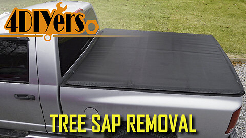
How to Remove Sap from a Vinyl Truck Tonneau Cover
How to remove tree sap from a vinyl tonneau cover. This can also be applied to other vinyl surfaces such as seats, other outdoor covers, vinyl roofs on cars, etc. Typically this can occur when a vehicle is parked under a tree, however there are no trees above my truck but there was a recent storm that blew some branches on the truck resulting in a bunch of sap being left behind. #detailing #cardetailing #carcare
Website: http://4diyers.com
Patreon: https://www.patreon.com/4diyers
Facebook: https://www.facebook.com/4diyers
Twitter: https://twitter.com/4DIYers
Instagram: https://www.instagram.com/4diyers/
Tumblr: http://4diyers.tumblr.com
Pintrest: https://www.pinterest.com/4diyers/
Tools/Supplies Needed:
-paper towel
-isopropyl alcohol
-vinyl condition
-soft clothes
Procedure:
By far the easiest method I have found is using isopropyl alcohol. It’s available in a couple of different versions, I have the strongest at 91%. The lesser strength stuff will work as well, it’ll just take slightly longer to soften up the sap. Depending on the quality of vinyl especially if it’s colored, it may be best to try this on a hidden area first ensuring you’re not damaging the color.
Apply the isopropyl alcohol to a paper towel, make sure it’s wet but not dripping, then rub the surface. Light to medium pressure is only needed, don’t get too aggressive where you’re stretching the material. You may be required to fold over the paper towel to a clean spot so you’re not smearing around the sap creating a larger mess. Even with the sap softened up, the residue can be spread around the area.
Once done, you can see that one spot of sap has been completely removed.
Continue this same method for the rest of the spots. Don’t dump the alcohol on the vinyl as it may dry out the material or bleach the coloring. Work at one spot at a time, apply more isopropyl alcohol as needed to the paper towel or flip it over to a clean spot as needed. You may need more paper towels as well if you’re running out of clean spots.
I would not recommend using a cloth as the sap residue will soak into the fabric. With a paper towel, it’s easy enough to throw away and replace. It’s important to remove this while it’s still fresh, so as soon as possible. When it hardens it becomes harder to remove and may even leave staining.
When done to prevent any bleaching which could potentially occur. Using a clean piece of paper towel with that isopropyl residue, go over a larger area to blend in the cleaning.
The isopropyl alcohol will evaporate very quickly so it won’t attack the surface as much as compared to a harsher solvent.
As a final step, the vinyl is now bare and has no protection. I would recommend using some form of conditioner, this will provide a layer of protection and soak into the material. Applications of products will vary, always be sure to read the product’s instructions.
Once done, now you can see we’re left with a clean sap free surface. Applying a condition more frequently also aids in preventing that sap from sticking to the surface well, almost like wax on the paint.
Thank you to all those who watch my videos and support my content. Don't forget to subscribe to my channel for future tutorial videos and like my video if you found it helpful. New videos are always being uploaded every week!
© 4DIYers 2013
All Rights Reserved
No part of this video or any of its contents may be reproduced, copied, modified or adapted, without the prior written consent of the author.
25
views
1
comment
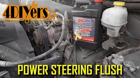
How to Change and Flush the Power Steering Fluid on a Dodge Ram
How to replace and flush out old power steering fluid in a third generation Dodge Ram. This is a 2006 1500 4x4 model with a 5.7L V8, procedures may vary based on your model or engine type. A similar procedure may also apply to other Dodge vehicles as well. For this truck, I will be upgrading to synthetic. This isn’t mandatory, it’s a personal preference. Looking in the owner’s manual, make sure you refer to yours as well to be safe, this truck requires ATF +4 automatic transmission fluid. The amount required is about 3.5 quarts or litres. From what I’ve been able to find, the fluid is to be replace every 120,000 km or 75,000 miles. #dodgeram #dodge #mopar
Website: http://4diyers.com
Patreon: https://www.patreon.com/4diyers
Facebook: https://www.facebook.com/4diyers
Twitter: https://twitter.com/4DIYers
Instagram: https://www.instagram.com/4diyers/
Tumblr: http://4diyers.tumblr.com
Pintrest: https://www.pinterest.com/4diyers/
Tools/Supplies Needed:
-interlocking pliers
-new power steering fluid
-drain pan
-funnel
-jack with stands
Chapters:
00:00 Intro
00:48 Disconnecting the Lines
01:27 Draining the Fluid
02:31 Flushing the System
03:00 Draining the Fluid Again
03:22 Reconnecting the Lines
03:44 Adding New Fluid
05:52 Bleeding the System
Procedure:
Going under the truck, make sure you have a drain pan handy. The easiest way is to remove the rubber lines off the cooler. These are held on with two crimp clamps. Using interlocking pliers, grab onto the clamps and pull them back from the connections.
Sometimes these rubber lines can stick, so you may need pliers to twist and help break them free. Having the pan close, grab onto the one line, twist and pull off. You may want to hold the steel line on the cooler so it doesn’t bend or damage it. You can just remove the lower line if you wish.
Then allow the fluid to drain. I used a strap to hold the lines down and direct them into the drain pan. To push out more fluid from the steering rack, turn the wheels full lock left to right. The front of the truck can be elevated, this will reduce drag when turning the wheels.
Another option is briefly starting the engine. Typically this is not something I like to do, however on this model of Dodge, there is no way to disable the engine starting. I started the truck and immediately turned it off. Do not run the engine any longer, no oil in the pump can cause damage.
To do a quick flush, I reconnected the lines. Reinstalled the clamps so the hoses don’t come disconnected. Make sure the area around the cap is clean on the reservoir, fill up the reservoir with new fluid. Start the truck and only let it run for about 15 seconds to circulate the fluid. And then turn the engine off.
Again disconnect the lines by removing the clamps and pulling off the hoses, then let the system full drain. You can turn the wheels or briefly start and turn off the engine if you wish. Loosening the reservoir cap can sometimes help with draining the system too.
Once the system is fully drained, reinstall the lines. Push the hoses on the connections ensuring they’re fully seated and pushed against the lips on the metal lines.
Then reinstall the clamps using the interlocking pliers. Add fluid to the system. Remove the reservoir cap and using a funnel, add fluid to the system. When the fluid no longer drops in level, with the front of the truck elevated to remove weight off the wheels, turn the steering wheel left to right, full lock to lock. Add fluid when the level drops. Again turn the wheels full lock left to right multiple times until the level stops dropping. Start the engine briefly and shut down, check the fluid level again. Add fluid again if needed.
Starting the engine again, let it run and turn the wheels full lock left to right. So no hold the steering against the lock as this can cause excessive strain on the pump. You may notice the pump whine briefly, this is normal as air is trapped in the system. Turn the wheel multiple times and keep checking the fluid level. Do this until all the air is bled from the system, so the fluid is a solid red color with no bubbling and the pump is quiet.
When done, shut the engine off and check the final level. The reservoir cap is equipped with a dipstick, it has level reading for when the system is hot and cold. The level should be half or 3/4 of the way between the low and high fill markings.
Thank you to all those who watch my videos and support my content. Don't forget to subscribe to my channel for future tutorial videos and like my video if you found it helpful. New videos are always being uploaded every week!
© 4DIYers 2013
All Rights Reserved
No part of this video or any of its contents may be reproduced, copied, modified or adapted, without the prior written consent of the author.
40
views
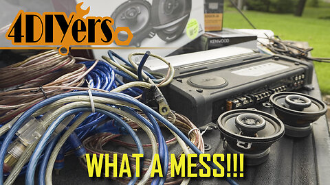
Redoing the Mess of an Aftermarket Audio System in my Dodge Ram
How to repair a poorly installed aftermarket audio system in your vehicle. I bought this truck with an already installed aftermarket audio system, this includes the head unit, front and rear speakers, and aftermarket amp. This truck doesn’t have the factory optioned amp from the factory. This was a pretty bad install and I typically avoid buying a vehicle that has an aftermarket sound system, but the price was right. I decided to repair this once the radio started acting up. Going over bumps would make the radio kick-off and hitting the dash would turn it back on. Some of the more specific areas have their own videos and this was done to save time as not everyone is working on the same vehicle. #oemtools #dodgeram #caraudio
Amazon Affiliated Links
US:
Trim metal retaining clips: https://amzn.to/3JyKt4j
12v 5 pin relay with pigtail: https://amzn.to/3sQZPe1
Assorted Automotive Phillips Trim Screws: https://amzn.to/3GWanxa
Kenwood Head Unit Replacement Harness: https://amzn.to/3uXfnj0
Pioneer 6-1/2" 3 Way Speakers: https://amzn.to/3v26e8V
Radio harness with Canbus module: https://amzn.to/3LEYP50
Kenwood KAC-M1814 Amplifier: https://amzn.to/3JAgSYe
Solder: https://amzn.to/2NnBKdM
Heat shrink: https://amzn.to/3s4FQ9y
Cable ties: https://amzn.to/2Maa0ZO
Electrical tape: https://amzn.to/2Zxy7o6
Canada:
Trim metal retaining clips: https://amzn.to/34LJGyk
12v 5 pin relay with pigtail: https://amzn.to/3rVWqva
Assorted Automotive Phillips Trim Screws: https://amzn.to/36m0We0
Kenwood Head Unit Replacement Harness: https://amzn.to/3v0IhP5
Pioneer 6-1/2" 3 Way Speakers: https://amzn.to/34FRVw1
Radio harness with Canbus module: https://amzn.to/3JAkWYM
Kenwood KAC-M1814 Amplifier: https://amzn.to/36at9UU
Solder: https://amzn.to/3blrYRC
Heat shrink: https://amzn.to/3s4FUWQ
Cable ties: https://amzn.to/3drYRyI
Electrical tape: https://amzn.to/3k4EVTy
OEMTOOLS 22588 13-in-1 Multi-bit Screwdriver: https://www.mobiledistributorsupply.com/22588-oemtools-22588-13-in-1-screwdriver-and-nut-driver-oem
OEMTOOLS 24498 Dual Temp Heat Gun: https://www.mobiledistributorsupply.com/24498-oemtools-24498-dual-temp-heat-gun-oem
OEMTOOLS 24487 20V Li-ion Brushless 1/4" Impact Driver: https://www.mobiledistributorsupply.com/24487-oemtools-24487-20v-max-li-ion-brushless-1-4-in-impact-driver-oem
Website: http://4diyers.com
Patreon: https://www.patreon.com/4diyers
Facebook: https://www.facebook.com/4diyers
Twitter: https://twitter.com/4DIYers
Instagram: https://www.instagram.com/4diyers/
Tumblr: http://4diyers.tumblr.com
Pintrest: https://www.pinterest.com/4diyers/
Tools/Supplies Needed:
-heat gun
-heat shrink
-new speakers
-new amplifier
-wiring
-crimp wire connectors
-split loop casing
-ratchet set
-screwdriver set
-drill with drill bits
-rubber grommet
-solder
-soldering iron
-nylon trim tool
Chapters:
00:00 Intro
00:40 Head Unit Removal
02:19 Front Speaker Removal
03:00 Rear Speaker Removal
05:14 Aftermarket Amplifier Removal
05:46 Aftermarket Wiring Removal
07:05 New Amplifier Location
08:36 Running the New Wiring
09:26 Making the New Audio Wiring Harness
13:46 Repairing the Speaker Connectors
15:29 New Rear Speaker Fitment
18:31 Finalizing the Amplifier Placement
19:11 Finalizing the Wiring
23:17 Installing the Relay
26:30 Final Look at the Wiring
28:39 Repairing and Modifying the Pillar Trim
30:39 Reassembling the Interior
Thank you to all those who watch my videos and support my content. Don't forget to subscribe to my channel for future tutorial videos and like my video if you found it helpful. New videos are always being uploaded every week!
© 4DIYers 2013
All Rights Reserved
No part of this video or any of its contents may be reproduced, copied, modified or adapted, without the prior written consent of the author.
33
views
Wrenches 101: Here's What you Need to Know
Everything you need to know about wrenches. What the most common wrenches are used in automotive repairs, along with their benefits, some comparisons and some tips. #tooltech #OEMTools #mechanic
OEMTOOLS 22217 40 Wrench Magnetic Organizing Rails: https://www.mobiledistributorsupply.com/22217-oemtools-22217-40-wrench-magnetic-organizing-rails-oem
Website: http://4diyers.com
Patreon: https://www.patreon.com/4diyers
Facebook: https://www.facebook.com/4diyers
Twitter: https://twitter.com/4DIYers
Instagram: https://www.instagram.com/4diyers/
Tumblr: http://4diyers.tumblr.com
Pintrest: https://www.pinterest.com/4diyers/
Chapters:
00:00 Intro
00:17 Combination Wrench
01:07 Open End Wrench
01:28 Box End Wrench
01:52 Line Wrench
02:32 Ratcheting Wrench
03:04 Crowfoot Wrenches
03:45 Specialty Wrenches
05:01 Open VS Box Ends
05:34 Interchangeable Sizes
06:47 Wrench Care & Storage
Combination wrench: this has both an open end and box end. The open and box ends are both the same size. The box end is available in both a 6 and 12 point versions. I’ll use these sockets as an example as I don’t have a 6 point wrench. A 6 point is a single hexagon, it has 6 vertices. These are great for maximum contact surface on a fastener, this means it’s able to handle more pressure reducing the chance of stripped that nut or bolt. A 12 point on the other hand, this is a double hexagon, it has vertices. A 12 point works great if you have a tight area with minimal movement for the wrench or if you’re working with a 12 point fastener. The downfall is that there’s a higher chance of stripped a fastener with a 12 point.
Open ended wrench: this is a wrench has two open ends. Each side will be a different size, one this large wrench the one side is 30mm and the other is 32mm. The main benefit is that you don’t need to carry as many wrenches and they can slip in from the side on a fastener.
Boxed end wrench: both sides are boxed, available is 6 and 12 point versions. Each end is a different size just like the open end wrench. These too allow one to cut back on the amount of tools they need to carry or store, they provide a better grip on fasteners but they are required to go over top of a fastener which may not be ideal in all situations.
Line wrench: just like the previous two styles of wrenches, these those are the same style on each end but will be a different size cutting back the need for more wrenches. They’re like a boxed end but with a cutout to fit over top of hydraulic, brake, or fuel lines. You’ll notice that they’re a 6 point to maximum surface contact on a fitting and they have a thicker profile to reduce the chance of the hex opening up. They simply fit over a line, this can be anything from a hydraulic, oil, fuel, air, or brake line.
If you were to use an open end on a fitting, there is a much higher chance of stripped the hex as it only has contact on two surfaces.
Ratcheting wrenches: they’re not a must have if you’re working on cars as a past time, but they do make life easier and are especially useful in a professional field to save time. However the biggest downfall is the cost as they can be quite expensive and they have moving components which could potentially fail or wear out. They’re great for working in tight places, they do have a slightly thicker profile on the box end, and the direction of movement is easily changed by flipping over the wrench.
Crowfoot wrench: an attachment rather than a tool that can be used by itself like a traditional wrench. It consists of an open end, this connects to a ratchet for working in awkward or tight spaces. This is another style which I rarely use, but you’ll definitely know when you’re in need of one. Before I had these, I ended up making my own and this was for the knock sensors on a BMW M62 V8. If these are being used with a torque wrench, if the crowfoot is perpendicular to the pivot point such as this, you’ll be applying the correct torque value to what your torque wrench is set as. But if the crowfoot is lower or higher than the pivot point such as this, a calculation is required to make adjustments to the required torque value.
Striking wrenches: as the name implies, those can be hit with a hammer to shock a fastener for loosening or tightening. Specialty wrenches aren’t typically needed for those of us working at home on our own projects, they tend to be more oriented to those working in the field.
Thank you to all those who watch my videos and support my content. Don't forget to subscribe to my channel for future tutorial videos and like my video if you found it helpful. New videos are always being uploaded every week!
© 4DIYers 2013
All Rights Reserved
No part of this video or any of its contents may be reproduced, copied, modified or adapted, without the prior written consent of the author.
13
views
Introducing my New Car!
This type of video is new, but I’m pretty excited about the new addition. After about 3 months of searching, I am the official owner of a 2010 BMW 335d. I managed to pick this up threw a wanted ad and the owner was about 45min away which was super convenient for me. I’m the third owner, as far as I know, the gentleman I purchased it from had it for about 10yrs and as you can see it’s extremely well kept. This is a warm State American car so it doesn’t have heated seats or a heated steering wheel unfortunately, but those are minor things especially with such a well-kept car. #foxwell #BMW335d #BMW
Foxwell NT530 Scanner: https://www.foxwelldiag.com/products/foxwell-nt530?variant=40625470537894&ref=5
Website: http://4diyers.com
Patreon: https://www.patreon.com/4diyers
Facebook: https://www.facebook.com/4diyers
Twitter: https://twitter.com/4DIYers
Instagram: https://www.instagram.com/4diyers/
Tumblr: http://4diyers.tumblr.com
Pintrest: https://www.pinterest.com/4diyers/
This is the fourth BMW I’ve owned and the 17th vehicle since I’ve been driving. So to start why I bought this car. I used to be a truck guy when I first started driving, but eventually got introduced to cars and grew a liking to them. As for how I got into BMWs, I have my mom to thank for that. She found my first BMW which was the 740i E32 and then she also found my 733i E23. Unfortunately life got crazy and I haven’t been able to dedicate as much time as I’d like to my E23, but hopefully I can get it sorted out this summer. That however is only a summer car. I missed having a BMW for a daily driver and with the insane fuel prices, there needs to be a more suitable replacement for the Ram. I still need a truck so the Ram isn’t going anywhere, with that being said though, mid 40mpg vs high teens mpg will be much easier on the wallet.
I also like having something rarer. For many, this is a very understated car. This had a limited run in North America only made between the years 2009 to 2011, only available in a sedan, and only in rear-wheel drive. Throughout the world, it was only available with an automatic however there is the odd manual conversion out there. At the time from what I’ve heard, BMW stated that they never produced a manual transmission strong enough to handle the power. This is an M57 3L inline 6 bi-turbo engine. It has 282hp and 428 ft-lbs of torque. Compared to an E90 M3, this has far more torque. And to top it off, this diesel has plenty of tuning potential. This car is stock other than the tint and wheels. It has E90 M3 staggered 19” wheels. 245 in the front and 265 in the rear.
If you’re new to BMWs or are unaware of this, some sites can be found through Google to decode your VIN, showing all the options your car is equipped with. Simple type in BMW VIN decoder and use one of the top results. I have found some will show a little more details than the other, so try to cross-reference between a couple.
While my car isn’t a sport package, it’s still spec’d well and not a base model. The color is Schwarz 2, the same color as my 540i which I believe is part of the 3 base colors BMW offered without paying extra. The other two are silver and white. This is a straight black with no metallic. It has black Dakota leather, from what I’ve seen on the E90 in Canada it’s hard to find them with leather. Most come with leatherette and will crack on the driver’s bolster both on the seat cushion and back. On the seat cushion it’s typically on the door side close to the separation on top and just above the plastic trim on the side. They’ll crack on the backrest too, again on the door side of the bolster. This happens at a low mileage too, it wasn’t meant to last sadly and this is why I prefer the leather. People will advertise it as being leather, this can be verified by decoding the VIN.
Moving onto the rear, apparently the brakes don’t have that many miles on them and I can see the pads are good. There is some rust on the rotors from sitting in the driveway for a couple of weeks and will hopefully clean up with a trip up the road and back. I pulled the rotors off to check the parking brakes and they’re in great shape. Most of the components are good here too except for the shocks which are badly leaking. So they’ll get replaced along with their bushings.
Thank you to all those who watch my videos and support my content. Don't forget to subscribe to my channel for future tutorial videos and like my video if you found it helpful. New videos are always being uploaded every week!
© 4DIYers 2013
All Rights Reserved
No part of this video or any of its contents may be reproduced, copied, modified or adapted, without the prior written consent of the author.
19
views
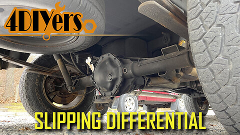
How to Troubleshoot a Worn or Slipping LSD Differential on a Dodge Ram
How to troubleshoot a slipping limited slip differential on a third generation Dodge Ram. Mopar refers to this as their Trac-Loc differential, this is the 9.25”. As many of you know, I did replace the oil in the differential a couple years ago. The differential didn’t have the proper maintenance intervals for the oil and unfortunately that can shorten the life of the clutches. #dodgeram #differential #mopar
Website: http://4diyers.com
Patreon: https://www.patreon.com/4diyers
Facebook: https://www.facebook.com/4diyers
Twitter: https://twitter.com/4DIYers
Instagram: https://www.instagram.com/4diyers/
Tumblr: http://4diyers.tumblr.com
Pintrest: https://www.pinterest.com/4diyers/
Tools/Supplies Needed:
-jack
-blocks
-torque wrench
-hub adapter
Chapters:
0:00 Intro
Procedure:
When I did replace the oil, it helped but a little while after it started chattering again. This is the most noticeable when turning at low speeds or while taking off from a stop. I will admit my driving style probably didn’t help already worn clutches either. After an oil change you’ll need to drive the truck in a figure-eight pattern 10 to 12 times, this will allow the fluid to work its way through the clutches and this may solve your issue. If not, the clutches will require a replacement.
Another method to determine worn clutches is by rotating the wheel by hand. First is blocking the front wheels so the truck doesn’t roll away. Then is jacking up one wheel on the rear axle so it’s off the ground, doesn’t matter which side. Put the transmission in neutral, do not start the engine.
You can remove the wheel and there is an attachment to fasten to the studs so you have a center pivot point for a torque dial to measure the resistance. But you can get a feel for it as well. An acceptable rating would be between 30 ft-lbs or 41 nm to 200ft-lbs or 271 nm. If it’s outside of this value, the clutches require a replacement.
A full rebuild is recommended while it’s apart. It’s peace of mind that you won’t have a component failure down the road and required splitting down the whole assembly again.
I did order the parts online and it’s extremely important to get good quality parts. If you cheapen out on something like the bearings, the whole job will need to be redone if they fail prematurely. Instead of buying everything separately, you can get kits. Of course you’ll need new oil, preferences will vary and you’ll need a friction additive which isn’t shown here.
Next are the outer bearings and seals which sits just behind the hubs. The axles need to be removed regardless, so most of the work is already done for the replacement of those components.
The other kit includes the bearings for the carrier and the front and rear of the pinion. Next is the crush sleeve, pinion nut, pinion seal, ring gear bolts, shims, thread locker, marking compound, an application brush and gasket. I did try to get the clutch pack but for whatever reason stock seems to be limited from different suppliers. The dealer wanted $600 just for the clutches, that wasn’t a realistic option for me as a new carrier was about $800 which includes the carrier, clutches, and spider gears. This is in Canadian dollars by the way.
I was planning on doing the rebuild myself, but due to some personal problems I decided against it and had a shop do it instead. Even finding a shop was a bit tough too as not everyone offers differential rebuilding. I ended up going with a shop that primarily works on transport trucks but specializes in transmissions too. The rebuild took then about 4-5 hours in total.
Once those clutches have been replaced, you’ll have a break-in period. As a generalized procedure, you’ll need to find an open parking lot where you can do a series of figure eights for about 30 minutes with light acceleration. This helps the clutches bed into each other.
Another issue worth noting with this model of differential is the retaining clips for the clutches as shown here. These are also known to back out and can get cause up in the gears chipping teeth. If the teeth are damaged, then a replacement is required.
Thank you to all those who watch my videos and support my content. Don't forget to subscribe to my channel for future tutorial videos and like my video if you found it helpful. New videos are always being uploaded every week!
© 4DIYers 2013
All Rights Reserved
No part of this video or any of its contents may be reproduced, copied, modified or adapted, without the prior written consent of the author.
44
views
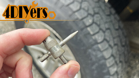
How to Use a 4 Way Valve Tool
How to use a four way tire valve tool. There are a couple different types of Schrader valve tools, this is one of them and is a combo tool consisting of four different tools in one. #wheels #tires #tooltech
Amazon Affiliated Links:
USA: https://amzn.to/3K8jL3s
Canada: https://amzn.to/3DHL0PW
UK: https://amzn.to/3uIJGYU
Website: http://4diyers.com
Patreon: https://www.patreon.com/4diyers
Facebook: https://www.facebook.com/4diyers
Twitter: https://twitter.com/4DIYers
Instagram: https://www.instagram.com/4diyers/
Tumblr: http://4diyers.tumblr.com
Pintrest: https://www.pinterest.com/4diyers/
First is removing the valve stem cap which will expose the Schrader valve.
Using the exterior thread chaser, this is used to clean up any damaged threads that are used for the cap. If you noticed, there’s a noticed out portions to allow for any debris to escape while straightening out any threads. Simply thread it on, then remove it, and this can be done a few times if they’re badly damaged.
This exterior thread chaser also has an alternative purpose. Replacing a valve stem, cutting off the old one.
The new one has a water and soap mixture applied for easier installation.
It’s inserted into the hole of the wheel, the tool is then threaded on.
The tool can be used as a “T” handle to pull through the new valve stem, ensuring it’s properly seated.
Next is using the Schrader valve core removal tool. The center of this is hollowed out for the valve push rod and it has notched out portions to lock onto the valve for removal and installation. Removing this valve is required to completely deflate the tire when it’s being unmounted or if you’re replacing the valve. Lock it into place, then turn counterclockwise to loosen and remove.
As a close up, here you can see the center portion fits inside the tool and then it locks onto the valve body.
The pointed tip is a reamer that is used to clean out the valve stem body. Sometimes excessive rubber from their’ construction or debris can plug up the hole cause fill or deflation issues. Stick it into the hole and rotate.
And finally is the thread chaser for the valve core threads inside the valve stem. Similar to the outside version, it’s noticed out on the sides to clean up the threads while allowing any debris to escape. Thread it into the stem and then remove it, this can be done a few times if needed.
Thank you to all those who watch my videos and support my content. Don't forget to subscribe to my channel for future tutorial videos and like my video if you found it helpful. New videos are always being uploaded every week!
© 4DIYers 2013
All Rights Reserved
No part of this video or any of its contents may be reproduced, copied, modified or adapted, without the prior written consent of the author.
21
views
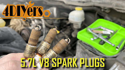
How to Replace the Spark Plugs in a 5.7L V8 Dodge Ram
How to replace the spark plugs on a third generation Dodge Ram 1500 5.7L V8 Hemi. This engine requires 16 spark plugs, two for each cylinder. Worn spark plugs will typically cause poor performance, poor fuel economy, hard starts, and engine misses.#OEMTOOLS #DodgeRam #Mopar
OEMTOOLS 22910 3/8 Inch Drive Ratchet (4 Inch) with Stubby Handle: https://www.mobiledistributorsupply.com/3-8dr-stubby-ratchet-1
OEMTOOLS 22417 Flexi-Tray Silicone Tool Tray Set - 3 Piece: https://www.mobiledistributorsupply.com/22417-oemtools-22417-suregrip-flexi-tray-3-piece-set-oem
Website: http://4diyers.com
Patreon: https://www.patreon.com/4diyers
Facebook: https://www.facebook.com/4diyers
Twitter: https://twitter.com/4DIYers
Instagram: https://www.instagram.com/4diyers/
Tumblr: http://4diyers.tumblr.com
Pintrest: https://www.pinterest.com/4diyers/
Tools/Supplies Needed:
-3/8" drive ratchet
-3/8" 3" & 6" extensions
-3/8" universal joint
-16 new spark plugs
-10mm and 5/8" sockets
-standard screwdriver or small pry tool
-penetrating oil
Chapters:
00:00 Intro
01:00 Driver's Side
03:44 Spark Plug Socket
04:19 Installing the New Spark plugs
04:42 Dealing with Seized Spark Plugs
05:51 Passenger Side
07:49 More Info On Removing Seized Spark Plugs
09:49 Reassembly
Procedure:
On driver side first was removing the electrical connectors on all the coil packs. Depress the tang on one side, then using a small pry tool or standard screwdriver, gently pry up the connector and remove. The wire to each connector is short so you can’t mix up their positions.
Remove the coil packs. Each coil pack is held in with two 10 mm bolts. Then pull out the coil pack. Each of the plug boots will have a seal around the plastic valve cover. These bolts don’t need to be fully removed from the coil pack just enough where they’re disconnected from the valve cover.
Vacuum cleaner is used to clean up any loose debris so it doesn’t fall down the holes. If your engine is excessively dirty that a vacuum cleaner would be recommended before removing the coil packs and after.
Finally are the last two coil packs on the driver side. The 3/8 drive ratchet with 10 mm can be used here too. For the very last coil pack with the bolt closest to the firewall, a 10 mm wrench may be easier. Both coil packs are lifted up to the top of the engine and can have the spark plugs boots bent giving you more movement.
Using a 5/8” deep socket for spark plugs, this has a rubber boot inside to remove and install the spark plugs. The first few plugs can be accessed with a 6 inch extension and a 3/8 drive ratchet. I was working one cylinder at a time removing the two plugs.
Install the new spark plugs, the torque specifications for the spark plugs are 13 ft-lbs or 18 Nm. If you are gapping the spark plugs, the required measurement is 0.045” or 1.14mm.
The last three plugs on this side are where I ran into the issue of them being seized. To overcome this, I put the truck back together and it took up for a drive up the road to get the engine up to full operating temperature. Once back I then remove the coil packs and applied penetrating oil around each spark plug. I then tried to loosen each spark plug. Any oil around the plug would soak into the threads. The plugs are also loosened and tightened to help work the oil into the threads and break away any debris. Do not force the plugs as you can damage the threads, if that is the case, you’ll be required to install a Heli coil.
To gain access to the spark plugs below the brake booster, I used my 3/8 drive ratchet with a 3 inch extension, a universal joint, and finally the deep socket.
On the passenger side, I was required to remove the colder intake. I did this more for viewing purposes than anything. If you have a factory airbox then you may be required to remove it.
Use the same processes on the other side, almost all the spark plugs on this side can be accessed with the 5/8” deep socket, the 6 inch extension, and the 3/8 drive ratchet. The very last spark plug requires the 3 inch drive ratchet with a 3 inch extension, the universal joint, and the deep socket.
Reinstall each of the coil packs. Tighten the 10mm bolts, and the torque specifications for the 10mm bolts are 62 in-lbs, not to be confused with ft-lbs or 7 Nm. Reassembly of components is in reverse of removal.
Thank you to all those who watch my videos and support my content. Don't forget to subscribe to my channel for future tutorial videos and like my video if you found it helpful. New videos are always being uploaded every week!
© 4DIYers 2013
All Rights Reserved
No part of this video or any of its contents may be reproduced, copied, modified or adapted, without the prior written consent of the author.
96
views

How to Scan BMW Fault Codes using a Foxwell NT530 Scanner
How to scan your BMW’s fault codes. On the newer BMWs, they have their own specific codes outside of the OBD2 versions. The problem with using a generic OBD2 Reader is that you may find yourself chasing around problems instead of focusing on a specific area. For this I’ll be using my 2010 #BMW 335D #E90 body style as an example. #Foxwell
Foxwell NT530 Scanner: https://www.foxwelldiag.com/products/foxwell-nt530?variant=40625470537894&ref=5
Website: http://4diyers.com
Patreon: https://www.patreon.com/4diyers
Facebook: https://www.facebook.com/4diyers
Twitter: https://twitter.com/4DIYers
Instagram: https://www.instagram.com/4diyers/
Tumblr: http://4diyers.tumblr.com
Pintrest: https://www.pinterest.com/4diyers/
Tools/Supplies Needed:
-Foxwell NT530 Scanner
Procedure:
-First is locating the OBD2 port. The OBD2 Port will be located within 3 feet or 91 cm of the steering wheel. On this, it’s located in the driver side footwell on the left side just as you open the door. There is a black cap that is labeled with OBD. Grab on the inside of the cap, unclip, and then pull off. It only clips on from one side and as you can see there are tabs that hold it into place on the opposite side.
Next is plugging in the diagnostic cable. Ensure is in the correct position and then push it into place.
Plug the diagnostic cable into the scanner. Once plugged in, then screw in the retaining fasteners. The scanner should automatically turn on.
To scan the codes the car should be in the on position. Insert the key fob into the port, then briefly press the start button. This will activate all the accessories in the vehicle.
Once the scanner is on, then select the BMW software. You can either enter the VIN manually or have a smart scan done. I have selected smart scan, this will automatically read the Vin and pull the information from your car. Then allow the scanner to load.
Next is selecting the diagnostics feature. Select quick scan, this will scan all the modules in the vehicle.
This will take a couple of minutes, the scanner will check for any fault codes across all the modules equipped in the vehicle. When a fault code is present this will be shown in the right column along with how many there are.
And as you can see we have four faults in the DDE control unit.
Clicking on this area we can see what exactly the fault codes are, Select read codes.
Here we can see that there are BMW specific ID numbers, different than the generalized OBD2 code numbers. Beyond that, we can also see each code has a description defining the problem area. Keep in mind a scan tool is used in the aid of diagnosing a problem, it won’t tell you exactly what needs to be replaced or done. The only way to remove a fault code permanently is to repair the problem. If a code is erased and the problem is not fixed, the code will reappear. We have a total of four fault codes here.
If you have solved the problem, simply go into the area where the code would be. I am using another module as an example. Click clear codes, give the scanner a moment to erase the codes and then you’ll be presented with a confirmation that they’ve been removed.
Now is an example using the generic OBD2 scanner process. This will extract codes as well but they may provide a broader range instead, not allowing you to pinpoint a problem as efficiently.
Once the scanner has completed its data collection, you can see we have 10 codes instead, on a more generalized scale.
Beyond reading those specific codes for BMW the scanner can also view ECU details, show live data, reset the oil light, register a new battery, brake deactivation, reset maintenance light, DPF regeneration, etc. those tutorials will be saved for future videos so be sure to keep an eye out for those.
Once you’ve logged those codes then you will need to take the appropriate steps to repair the issues. After that is disconnecting the scanner and then turn off your ignition.
Thank you to all those who watch my videos and support my content. Don't forget to subscribe to my channel for future tutorial videos and like my video if you found it helpful. New videos are always being uploaded every week!
© 4DIYers 2013
All Rights Reserved
No part of this video or any of its contents may be reproduced, copied, modified or adapted, without the prior written consent of the author.
37
views
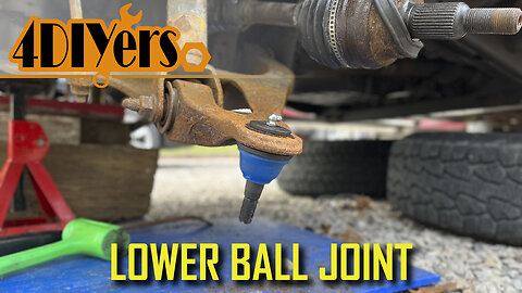
How to Replace the Lower Ball Joints on a 2002-08 Dodge Ram
How to replace the lower ball joints on a third generation Dodge Ram 1500. This is a 2006 4wd model. Loose or worn ball joints can cause uneven tire wear, steering wandering, clunking, stiff steering, and in a severe situation cause the steering knuckle to disconnect while driving. #dodgeram #oemtools #mopar
OEMTOOLS 22649 Pliers Set: https://www.mobiledistributorsupply.com/22649-oemtools-22649-4-piece-pro-mechanic-s-pliers-set-oem
Website: http://4diyers.com
Patreon: https://www.patreon.com/4diyers
Facebook: https://www.facebook.com/4diyers
Twitter: https://twitter.com/4DIYers
Instagram: https://www.instagram.com/4diyers/
Tumblr: http://4diyers.tumblr.com
Pintrest: https://www.pinterest.com/4diyers/
Tools/Supplies Needed:
-new ball joints
-ball joint press
-jack and stands
-21mm and 35mm sockets
-ratchet set
-ball joint separator
-hammer
-large interlocking pliers
-torque wrench
-wire brush
-snap ring pliers
Procedure:
Elevate the front of the vehicle and remove the wheel. Remove the center cap. Reinstall the wheel and lower the wheel down onto the ground.
Using an 35mm socket with a Johnson bar to loosen that axle nut. Elevate the vehicle again and remove the wheel.
Loosen the master cylinder reservoir cap. Loosen the two 21mm bolts holding on the caliper and caliper carrier. Compress the pistons in the caliper using large interlocking players. Remove the caliper assembly and tie it up to the frame using a bungee cord. Remove the rotor.
Remove the cottter pins on the upper ball joint, lower ball joint, and tie rod using pliers. Finish removing that 35mm axle nut.
Use a brass or lead hammer and hit the tip of the axle shaft spline. Using the appropriate sized sockets, loosen the upper ball joint, tie rod, and lower ball joint.
The tie rod was removed. Finish removing the nut on the upper ball joint. Using a ball joint spreader, separate the upper ball joint from the steering knuckle.
Use a strap to hold up the axle once that steering knuckle has been removed.
Use a ball joint seperator to break the lower ball joint free. Disconnect the axle. Then remove the steering knuckle.
Use a wire brush to clean up around the mounting point on the lower ball joint. Using snap ring pliers and a standard screwdriver, remove the snap ring. If equipped with a grease fitting, use a small wrench to remove it.
Using the appropriate attachments to press out the old ball joint. Clean up the area around the ball joint with a wire brush. Compare the old and new ball joints to ensure they are the same. The new ball joint will need to be installed without the grease boot. Make sure the adapters for the ball joint press and the control arm are clean and free of any debris which could potentially fall into the new grease. Use the appropriate adapters to push the new ball joint into place. You can start it into place first with something flat on the top side. Then you’ll need to switch to an adapter which has free movement to push it above the control arm surface for the snap ring. The bottom flange of the ball joint should be firmly pushed against the bottom of the control arm.
Install the grease boot. These are a serviceable ball joint so they do have a grease fitting. Install the grease fitting using a small wrench. Install the new snap ring using snap ring pliers.
Reinstall the steering knuckle. First the axle was pushed back into the wheel bearing and then the lower ball joint was connected. The castle nut was installed by hand so everything is held into place. The lower control arm was jacked up slightly to put some weight on it so it’s easier to connect to the upper control. Thread on the axle nut.
Due to the tension on the bushings you’ll need a prybar to pull down that upper control arm into the steering knuckle. Then the castle nut was installed.
Reinstall all other components in reverse of removal. The upper ball joint torque specification is 40ft lbs or 54 nm. The tie rod nut torque specification is 45 ft lbs or 61 nm. And the lower ball joint torque specification is 38 ft lbs or 52 nm.
Align the holes for the castle nuts on the various components, then install the cotter pins. The torque specifications for the caliper carrier bolts are 130 ft-lbs or 176 nm. The torque specifications for the lug nuts is 135 ft-lbs or 183 nm. The wheel is then lowered onto the ground and as a last step that half shaft nut is torqued to 185 ft lbs or 250 nm.
Thank you to all those who watch my videos and support my content. Don't forget to subscribe to my channel for future tutorial videos and like my video if you found it helpful. New videos are always being uploaded every week!
© 4DIYers 2013
All Rights Reserved
No part of this video or any of its contents may be reproduced, copied, modified or adapted, without the prior written consent of the author.
80
views
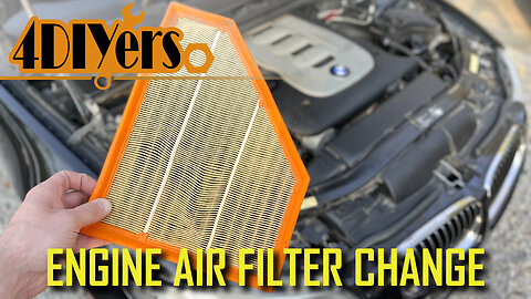
How to Replace the Engine Air Filter on BMW 335d E90
How to replace the engine air filter on a BMW 335D E90 body style. A similar procedure may also be used on other BMW models with the same engine. This is the M57 3L inline 6 cylinder. A dirty or plugged air filter can cause a variety of issues consisting of poor fuel economy, poor performance, throttle hesitation, and even throwing an engine code. #turnermotorsport #foxwell #bmwe90
Engine air filter: https://click.linksynergy.com/deeplink?id=N/DVI*Mr8tI&mid=43304&murl=https%3A%2F%2Fwww.turnermotorsport.com%2Fp-582285-air-filter%2F
Foxwell scanner: https://www.foxwelldiag.com/products/foxwell-nt530?variant=40625470537894&ref=5
Website: http://4diyers.com
Patreon: https://www.patreon.com/4diyers
Facebook: https://www.facebook.com/4diyers
Twitter: https://twitter.com/4DIYers
Instagram: https://www.instagram.com/4diyers/
Tumblr: http://4diyers.tumblr.com
Pintrest: https://www.pinterest.com/4diyers/
Tools/Supplies Needed:
-standard screwdriver
-brush
-vacuum
-bottle of water
-new engine air filter
Procedure:
Here I’m using my Foxwell NT530 OBD scanner. A BMW specific scanner is recommended to pull the proper codes. Generic OBD2 codes can send you on a chase trying to sort out those issues. If you do you have a check engine light and if that code is 4D76 for the charging air temperature sensor, this can potentially be a plugged air filter. A friend of mine told me about this issue, it’s quite common amongst diesel BMWs.
First is opening the hood, the air filter is located on the left side when facing the front of the car. There are three latches on the airbox, one on each side and one at the rear. The top cover locks into the bottom cover behind the headlight.
This can be pulled up to replace the filter, however it is a good idea to clean your airbox before installing a new filter. Using a standard screwdriver, loosen the intake hose gear clamp. This will allow us to remove the top cover of the airbox, and place it off to the side.
There is no need to disconnect the sensor wire.
As you can see there is quite a bit of debris on the old air filter and in the airbox. Using a vacuum cleaner, remove as much of the debris as possible. The assistance of a brush can be used to help agitate the surface, loosening up any debris.
After that was using another brush with a bottle of water. Soap can also be used if you wish. There are drain holes in the bottom of the airbox, therefore there’s no issue with pooling water. It’s always important to make sure those drain holes are not plugged either. Starting with a clean air box before the new filter is installed will prolong the life of your air filter.
Compare the old and new air filters to ensure they are the same. As you can see the older filter is quite dirty then compared to the new replacement.
With the airbox dry, a new air filter can be installed. Push the new air filter into place, ensuring it is properly seated around the perimeter.
Install the air box cover and clip it back onto the intake hose. Make sure the filter doesn’t push off when locking the cover into place.
Then lock the latches into place.
Finally is finishing up with tightening the gear clamp.
If you do have an engine code, the code may disappear over time with driving. However you can also clear the codes using the Foxwell NT530 Scanner. I do have a video that goes more into depth on using the scanner. That’s a brief overview, you would plug the scanner in and turn the ignition to the on position Without the engine running.
Select the pre-loaded BMW diagnostic feature, then scan the codes. Once the scanner is done you can select the option to clear the codes.
Thank you to all those who watch my videos and support my content. Don't forget to subscribe to my channel for future tutorial videos and like my video if you found it helpful. New videos are always being uploaded every week!
© 4DIYers 2013
All Rights Reserved
No part of this video or any of its contents may be reproduced, copied, modified or adapted, without the prior written consent of the author.
26
views
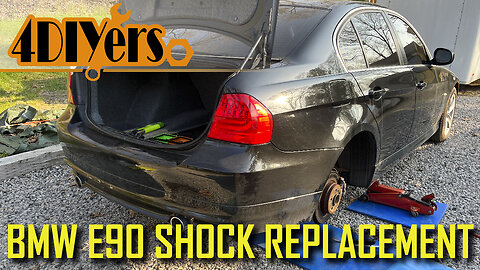
How to Replace the Rear Shocks on a BMW E90 3 Series
How to replace the rear shocks on a BMW E90 3 Series. This particular car I am working with you today is a 2010 335d sedan. This tutorial will cover how to remove the trunk liners, replacing the lower shock mount, and installed upgraded upper polyurethane shock mounts. #turnermotorsport #bmwe90 #bmw3series
Shocks: https://bit.ly/3II13Qj
Shock mounts: https://bit.ly/3P9Q2t7
Bump stops: https://bit.ly/3yKTUd7
Polyurethane bushings: https://bit.ly/3aCjDg9
Website: http://4diyers.com
Patreon: https://www.patreon.com/4diyers
Facebook: https://www.facebook.com/4diyers
Twitter: https://twitter.com/4DIYers
Instagram: https://www.instagram.com/4diyers/
Tumblr: http://4diyers.tumblr.com
Pintrest: https://www.pinterest.com/4diyers/
Tools/Supplies Needed:
-E12 socket
-nylon trim tool
-jack with jack stand
-new shocks, shock bushings, and shock mounts
-17mm socket with johnson bar
-6mm socket
-16mm wrench
-3/8" drive ratchet
-phillips and standard screwdriver
Chapters:
00:00 Intro
00:42 Passenger Side
00:53 Disabling Trunk Light
01:06 Trunk Liner Removal
02:52 Top Shock Mount
03:04 Bottom Shock Mount
03:29 Shock Removal
03:47 New Shock Assembly
06:39 Installation of New Shock
07:57 Driver's Side Replacement
11:09 Wheel Installation
Procedure:
Safely elevate the vehicle and use a jack stand. Using a 17 mm, remove the lug studs. The trunk will be open for quite a long time so it’s a good idea to deactivate the trunk light. This can be done by flipping the latch into the closed position using a screwdriver. Make sure you do release this before closing the trunk after.
Using a standard screwdriver remove the two plastic caps on the top of the rear trunk trim. This will expose to Philip screws which need to be removed. There will be two clips which need to be removed on each side. Lift up the trunk liner. Pull up the gasket along the backside of the trim. Lift up the trim slightly from the backside and then push it forward to disconnected from the loops. Remove the trunk liner.
Remove the trunk liner on the passenger side, there will be four black plastic clips which need to be removed. One will be hidden behind the removable panel which exposes the battery. Flip out the panel, lift out and remove the last clip then. Push the seat forward and then pull out the liner. Remove the rubber cap covering the top of the strut mount.
Using a ratchet with a 6 mm socket, this will be used to hold the center shaft of the shock. The nut uses a 16 mm. Remove the nut, it will be attached to a plate along with a rubber bushing.
On the bottom of the shock you'll need to remove the two E12 bolts. The shock can be compressed by hand, then work out the rubber mount from the control arm by hand. A small pry tool may help in the assistance of the removal. You don’t need to tilt the top out and to the back, that’s the easiest method I found.
For assembling the new shocks with polyurethane bushing, the top bushing cap will need to be separated, we will be reusing the large metal washer and nut. Installing the bottom bushing, remove the locking nut from the bottom of the shock, install the new rubber bushing, and then install and tighten the nut. The bushings can be installed first in the car as well, it’s personal preference. There is a spot on the shock for wrench so the nut can be properly tightened. Both the spot on the shock and the nut use a 17mm. The torque specifications for that nut is 28 ft-lb or 38 Nm.
The metal cap from the old bumps stop will need to be reused. Insert these components onto the shock shaft.
Install the first part of the polyurethane bushing. Using the supply lubricant, apply to the faces where it will be touching any objects along with the center where the shaft is slid through. Install the rubber cover.
Apply more lubricant to the bushing and install that as well.
Back at the car, compress the shock and insert the bottom portion with the bushing into the control arm. I made sure the top portion is inserted into the hole. Then install the two bolts. The torque specifications for these bolts is 44.2 ft-lb or 60 Nm. I did raise the control arm with a jack slightly to help push the shock into place. This bushing did have lubricant apply to the mounting faces and center hole. Depending on the shock used, the torque specifications for the nut at the top if it’s an M10, it’ll be 19.9 ft lbs or 27 Nm. If it’s n M14, it’ll be 27.2 ft lbs or 37 Nm.
All other parts are installed in reverse of removal. The torque specifications for the rear wheels is 88.5 ft lbs or 120nm.
Thank you to all those who watch my videos and support my content. Don't forget to subscribe to my channel for future tutorial videos and like my video if you found it helpful. New videos are always being uploaded every week!
© 4DIYers 2013
All Rights Reserved
No part of this video or any of its contents may be reproduced, copied, modified or adapted, without the prior written consent of the author.
29
views
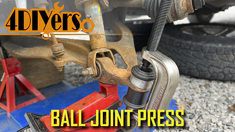
How to Use a Ball Joint Press
How to use a ball joint press. This video includes the removal and installation of the pressed in ball joints into a control arm. For this example I will be using my 2006 dodge ram. Here I’m using my OTC kit model number 7249, there are various kits available. It’s always important to invest in something which is a good quality so it doesn’t let you down part way through a job #balljoint #suspension #mechanic
Amazon OTC ball joint press links
USA: https://amzn.to/3zAGimp
Canada: https://amzn.to/3JbsZvO
Website: http://4diyers.com
Patreon: https://www.patreon.com/4diyers
Facebook: https://www.facebook.com/4diyers
Twitter: https://twitter.com/4DIYers
Instagram: https://www.instagram.com/4diyers/
Tumblr: http://4diyers.tumblr.com
Pintrest: https://www.pinterest.com/4diyers/
Tools/Supplies Needed:
-ball joint press
-ball joint separator
-hammer
-gear oil
-new ball joints
-pliers
-ratchet and socket set
Procedure:
Remove the wheel, procedures for accessing the ball joint will vary between vehicles. Considering this truck is four-wheel drive, I will be removing the steering knuckle to access the lower ball joint. Therefore the axle needs to be disconnected.
Ball joints may be equipped with a stover nut or castle nut. In the case of a castle nut, a cotter pin will need to be removed. The cotter pin needs to be straightened out and then pulled through the whole using pliers.
To disconnect the taper on the ball joint from the steering knuckle, a ball joint separator is used. You can also hit the start with the hammer or use a pickle fork. This is an aluminum steering knuckle, do not hit it with a hammer as you do risk cracking it.
Use the ball joint separator to disconnect the lower ball joint. When removing the steering knuckle, the spline will need to be disconnected from the wheel bearing on this four-wheel-drive truck.
Using a wire brush, clean around the ball joint. This will remove any debris so we can determine if a clip is required to be removed and no debris binds up around the ball joint when it’s being pressed out of its position.
Using snap ring pliers, remove the snap ring. Ross can sometimes hold these snap rings in place so the assistance of a standard screwdriver may be required.
This is a serviceable ball joint, the grease fitting will need to be removed. With this removed, we will have a flat surface for the press to push on.
Oil the threads on the press using gear oil. This will ensure there is no binding and you’re not causing any damage to the threads of the press.
The ball joint will have a lip on the one side where it holds it into place. On the opposite side is where the snap ring is located. The snapper inside is where the ball joint is pushed from. The threaded rod will push down onto the ball joint, on the other side there will be a sleeve and a face plate where the opposite side of the C frame of the press locks on to. When the press is tightened, this will push the ball joint down and it has free space for movement within that sleeve. The sleeve should be larger than the ball joint retaining ring.
Once that ball joint has been removed, use a wire brush to clean up any rust or debris around the face and inner bore of where that ball joint would be located.
Always ensure the attachments for your ball joint press is clean. This particular ball joint doesn’t have a boot installed at the moment, this will be installed after. There is exposed grease and contaminants can stick to this.
Use a sleeve that can fit on the ring of the ball joint. You’ll need free space so the ball joint can push through without any obstructions.
Depending on the distance, you may need to change attachments as the press doesn’t open up wide enough. Tighten the press so the ball joint is slowly pushing in. Remove the ball joint press so you can switch attachments to fully push through. Tighten the ball joint press until that ball joint is fully seated.
Install the boot to protect the joint. This particular brand does come with an installation cup to push on the boot.
If you have a serviceable ball joint, the next step is installing the grease fitting. Make sure the grease fitting is angled in such a way so it doesn’t interfere with the steering knuckle and can be easily accessed.
Using snap ring pliers, install the new snap ring for the ball joint. A standard screwdriver may be required to help push down that snap ring and shirts for seated.
Install all other parts in reverse of removal.
Thank you to all those who watch my videos and support my content. Don't forget to subscribe to my channel for future tutorial videos and like my video if you found it helpful. New videos are always being uploaded every week!
© 4DIYers 2013
All Rights Reserved
No part of this video or any of its contents may be reproduced, copied, modified or adapted, without the prior written consent of the author.
47
views

How to Change the Cabin Filter on a BMW 3 Series E90
How to replace the cabin filter on a BMW E90 body style. This particular car I am working with you today is a 2010 335d. A plugged cabin filter can cause issues such as an odor in your interior, poor performance of your AC system, and even shorten the life of your HVAC blower motor #turnermotorsport #bmw3series #bmwe90
Air filter link: https://bit.ly/3zBdPwU
Website: http://4diyers.com
Patreon: https://www.patreon.com/4diyers
Facebook: https://www.facebook.com/4diyers
Twitter: https://twitter.com/4DIYers
Instagram: https://www.instagram.com/4diyers/
Tumblr: http://4diyers.tumblr.com
Pintrest: https://www.pinterest.com/4diyers/
Tools/Supplies Needed:
-8mm socket on screwdriver handle
-new replacement cabin filter
-vacuum cleaner
-clean rag
-brush
-bottle of water
Procedure:
First is opening the hood. You’ll find the cabin filter is located at the back of the engine bay just below the windshield. There is a big plastic panel that needs to be removed and is held in with 6 8mm screws.
Once the screws have been removed, then lift off the cover.
Before installing the new Air filter, I would recommend using a vacuum cleaner and a brush to clean up any loose debris. Cleaning the debris up will prolong the life of your new replacement cabin filter.
A bottle of water with a brush can also be used. Rinse the area sufficiently, there are drains on each side. If the water doesn’t fully drain due to how your vehicle is sitting, a wet-dry shop Vac can be used.
Now on to the cover. Disconnect the cabin filter from the front side by the three clips first and then lift it out of its position.
Again I would recommend cleaning the cover ensuring there is no dust or debris. Also clean the gaskets on the backside to ensure they properly seal.
Finally is installing the newer filter. Clip it onto the backside first and then snap it into place on the front side. Insured it properly seated. If you do find your cabin filter cover is broken, new replacements can be purchased.
Finally reinstalling the assembly back onto the car. Make sure it’s in the correct position and then install those 6 8mm screws.
After that, you’re officially done.
Thank you to all those who watch my videos and support my content. Don't forget to subscribe to my channel for future tutorial videos and like my video if you found it helpful. New videos are always being uploaded every week!
© 4DIYers 2013
All Rights Reserved
No part of this video or any of its contents may be reproduced, copied, modified or adapted, without the prior written consent of the author.
15
views
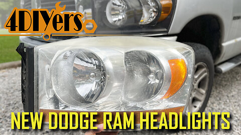
How to Upgrade or Replace the Headlights in a Dodge Ram using Nilight Lights
How to upgrade the factory headlights in a third generation Dodge Ram using the custom lights from Nilight. My old headlights are faded. I did polish them in the past using the wet sanding with the compound method, however that’s not a permanent fix. I’m also not a huge fan of the chrome, so something which cuts back on this is an ideal upgrade for me. Here you can see the new replacements. These still maintain a chrome reflector which is needed however the surrounding area is a satin black. With my truck being a 2006, it was the only year available with the bottom orange light. Therefore the new lights will give the impression the truck is slightly newer. #dodgeram #nilight #mopar
Amazon headlight links:
USA: https://amzn.to/3zEUfyw
Canada: https://amzn.to/3P2eZWz
Nilight Website: https://www.nilight.com/
Website: http://4diyers.com
Patreon: https://www.patreon.com/4diyers
Facebook: https://www.facebook.com/4diyers
Twitter: https://twitter.com/4DIYers
Instagram: https://www.instagram.com/4diyers/
Tumblr: http://4diyers.tumblr.com
Pintrest: https://www.pinterest.com/4diyers/
Tools/Supplies Needed:
-10mm socket with ratchet
-3" and 6" extension
-tape measure
-phillips screwdriver
-electrical tape
-nylon trim tool
Procedure:
Open the hood, this is needed to access the fasteners behind the grill. Remove the two 10 mm bolts using a 3/8 drive ratchet with a 3 inch extension. On the inside of the fender will be a rubber cap that needs to be removed. A 3 inch extension can be used, however a 6 inch extension does make it easier. Using a nylon trim tool, gently pull out the headlight from the side of the fender to disconnect it.
Then twist out the headlight bulb, the signal light bulb, and the parking light bulb. These simply turn, then pull straight out.
The bottom parking light bulb will need to be capped off so it’s not affected by any moisture. Removing this bulb won’t cause any errors on the dash. The connector was cleaned and then electrical tape was wrapped around it so it’s protected from any moisture or dirt. After that the connector is then cable tied off in the background so it doesn’t interfere with anything.
First was installing the headlight bulb with the connector. This is simply pushed into place and then rotated clockwise to lock it in. I tried to reuse the old signal light bulb socket however I did find it doesn’t lock in as well. Therefore I was using the supplied sock instead. Two tangs need to be depressed on the electric connector to disconnect it from the socket, then pull it straight out. Install the bulb into the new socket, twist it into place, and then reconnect the electrical connector.
The new lights come supplied with clips at the top corners. If yours are still in good condition, these can be removed and you can reuse the factory versions. The light is then pushed into place. Ensure all the slots lineup and then clip it into place.
Start the fasteners by hand. I tightened the nut inside the fender well first. I did find the threaded stud is slightly longer so a deep socket is required instead. Once done, the rubber plug is then installed.
Tighten the two 10 mm bolts on the grill side then.
Finally the plastic protector can then be removed. I left this in place to ensure the lens wouldn’t get damaged during the installation.
Now onto the passenger side for additional angles. Repeat the same procedure.
You’ll need to find a level surface with a wall where you’re able to park the vehicle 25 feet away to get a proper reference point for the beams.
You can drive the vehicle up against the wall and take a reference point of where the beam is. The door I’m using here for a reference does have lines, and additional aid can be using tape to reference the top of the beam.
Now the vehicle is reversed back to 25 feet from the wall. The 25 foot mark is taken from the front of the headlight. The vehicle needs to be perpendicular to the wall. Turn off your fog lights.
Now the headlights can be adjusted, as you can see as I move the adjustment screw the beam pattern does move. The top of the brightest portion of the light line needs to be at the same level as the lightbulb within the headlight assembly. Clockwise goes up and counterclockwise goes down.
I typically like to go back to the wall and take a visual view as well.
Once done you can then check the high beam pattern. There is no adjustment for the high beams, the low beam and high beam assembly are in one.
Thank you to all those who watch my videos and support my content. Don't forget to subscribe to my channel for future tutorial videos and like my video if you found it helpful. New videos are always being uploaded every week!
© 4DIYers 2013
All Rights Reserved
No part of this video or any of its contents may be reproduced, copied, modified or adapted, without the prior written consent of the author.
16
views
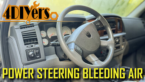
How to Bleed the Power Steering System on a Dodge Ram
How to bleed the power system of air in a third generation Dodge Ram. This is a 2006 1500 model equipped with a 5.7L V8, however this is a generic procedure that can be applied to other models or vehicles as well. Bleeding the system of air is required when the fluid is replaced, a component has been replaced where it requires the fluid to be drained, or if an excessive amount of fluid has leaked out. Low fluid or air in the system, you may notice excessive pump whining or the pump cavitating and your steering may be hard to operate. Prolonged usage with low fluid or having air in the system can damage the power steering pump. #dodgeram #powersteering #mopar
Website: http://4diyers.com
Patreon: https://www.patreon.com/4diyers
Facebook: https://www.facebook.com/4diyers
Twitter: https://twitter.com/4DIYers
Instagram: https://www.instagram.com/4diyers/
Tumblr: http://4diyers.tumblr.com
Pintrest: https://www.pinterest.com/4diyers/
Tools/Supplies Needed:
-power steering fluid
-funnel
-clean rag
Procedure:
It’s always important to refer to your owner’s manual to determine what fluid is required for your vehicle. For this model of truck specifically, it takes Mopar ATF +4.
With the engine off, start by opening the hood and locating the power steering fluid reservoir.
One this truck, it’s above the pump on the driver’s side.
Remove the cap, the cap is equipped with a dipstick to determine the fluid level when the system is either hot or cold. The level readings are different on each side of the dipstick.
A funnel is best, add fluid to the system. Careful not to add too much where it can spill out and do not get oil on the belt. Ensure the reservoir has fluid inside.
With the engine still off, elevating the front of the vehicle with the weight of the wheels does help. Put the key in the ignition to disable the steering lock, then turn the steering wheel full lock to lock left and right.
Do this multiple times, check the fluid level every few times and add more fluid as needed.
Do this until the fluid level stops dropping in level.
Next is starting the engine for a moment, then turning it off and checking the fluid level again. This operates the pump where it builds up pressure, forcing fluid through the system and potentially letting any air out. Then add fluid again if needed.
The fluid is normally red, but here you can see it’s a pink color with bubbling, this means there is air in the system. When the system is properly bled and no air is present, the fluid will be a solid red.
Start the engine again this time leaving it running, then turn the wheel full lock to lock left and right. Do not hold the wheel at the lock position for a longer time as this too can damage the pump. Do this multiple times, and keep monitoring the fluid level.
Add fluid as needed, once it stops dropping, continues operating the wheel a few more times and then stop. How long this takes depends on how much air is in the system.
When done, depending on the engine temperature, check the finalized fluid level using the dipstick on the cap. Typically I like to keep it between the minimum and maximum lines.
Thank you to all those who watch my videos and support my content. Don't forget to subscribe to my channel for future tutorial videos and like my video if you found it helpful. New videos are always being uploaded every week!
© 4DIYers 2013
All Rights Reserved
No part of this video or any of its contents may be reproduced, copied, modified or adapted, without the prior written consent of the author.
10
views
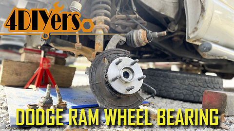
How to Replace the Front Wheel Bearings on a Dodge Ram 1500 4wd
How to eplace the front wheel bearings on a third generation 4wd Dodge Ram. I’m working with a 2006 1500 model. While I was doing the ball joints, I happened to catch light clicking in the wheel bearings so they are coming to the end of their life span. It’s apart now so it’s best to replace them now and save on the extra work after. Worn wheel bearings can cause excessive growling, you can feel some roughness when rotating by hand and they can also cause an ABS fault. I do have a video for what a faulty wheel bearing sounds like so be sure to check it out. #dodgeram #mopar #dodgetrucks
Website: http://4diyers.com
Patreon: https://www.patreon.com/4diyers
Facebook: https://www.facebook.com/4diyers
Twitter: https://twitter.com/4DIYers
Instagram: https://www.instagram.com/4diyers/
Tumblr: http://4diyers.tumblr.com
Pintrest: https://www.pinterest.com/4diyers/
Tools/Supplies Needed:
-35mm, 21mm, 8mm, 18mm sockets
-ratchet set
Procedure:
Remove the wheel. Pop out the center cap. Reinstall the wheel, then lower the wheel down onto the ground. Use a 35mm socket with a Johnson bar to loosen that axle nut. Remove the wheel again.
Loosen the master cylinder reservoir cap. Loosen the two 21mm bolts holding on the caliper and caliper carrier. Compress the pistons in the caliper. Remove the caliper assembly and tie it up to the frame using a bungee cord. Remove the rotor.
Remove the cotter pin on the tie rod, then remove the castle nut and finally disconnect the tie rod.
I removed the fender liner to gain access to the ABS sensor wire. The wheel liner is held on with a couple of 8mm bolts. Push the fender liner down towards the frame and then you’ll be able to unclip it from around the fender. After that is pulling the fender liner straight out.
As for disconnecting the electrical connector for the ABS sensor, there will be a red clip that needs to be pulled out. A standard screwdriver is best for this. Then pull apart the connector.
Remove the cotter pins for the upper and lower control arms, then remove the nuts. A hammer can be used to hit the stud upward for disconnecting the taper on the ball joint. The threaded stud was spinning for the lower ball joint so I ratchet and socket was required while using a wrench to remove the nut. Finish removing the half shaft 35mm nut.
Finally is removing the steering knuckle. Pull the axle shaft out, and make sure the joint doesn’t pull apart.
Using a wire brush, clean up the exposed threads of the three bolts holding on the wheel bearing. Apply some penetrating oil to these exposed threads. By far the easiest method I found was using an impact on all three of these 18mm bolts.
Set up the steering knuckle on a wood block and using a large hammer, hit out the wheel bearing for the backside. Eventually it’ll fall out with the backing plate. If there is any corrosion on the steering knuckle, a file is to efficiently clean it off so we have a clean mounting face for the new wheel bearing. Then I finished up with sandpaper.
All three of those bolts were cleaned up using a wire brush and brake cleaner. Place the new wheel bearing face down, install the dust shield and finally the steering knuckle. Make a note of the orientation for the ABS sensor and dust shield.
I applied a medium grade thread locker to each of the bolts and then install it. They are first tightened up using the electric impact. The torque specification for each of these 18 mm bolts is 120 ft lbs or 163 Newton meters.
Reinstall the steering knuckle. Install the axle spline first, pull the spindle up onto the lower ball joint and thread on the nut. The lower control arm can be jacked up slightly to help push it into place for the upper control arm. Using a prybar, pull down the upper control arm and insert the taper for the ball joint. Thread on the castle nut.
The torque specifications for the upper ball joint torque specification is 40ft lbs or 54 nm, he tie rod nut is 45 ft lbs or 61 nm and th lower ball joint is 38 ft lbs or 52 nm. Install the cotters pins for the upper ball joint, lower ball joint, and tie rod.
Clean the rear of the rotor from any rust and then install. Install the brake caliper with carrier. The torque specifications for the caliper carrier bolts are 130 ft-lbs or 176 nm.
Reconnect the ABS sensor and clip in the wire. The fender liner can then be reinstalled.
Install the wheel. The torque specifications for the lug nuts is 135 ft-lbs or 183 nm. The wheel is then lowered onto the ground and the half shaft nut is torqued to 185 ft lbs or 250 nm. That center cap is installed.
Thank you to all those who watch my videos and support my content. Don't forget to subscribe to my channel for future tutorial videos and like my video if you found it helpful. New videos are always being uploaded every week!
© 4DIYers 2013
All Rights Reserved
No part of this video or any of its contents may be reproduced, copied, modified or adapted, without the prior written consent of the author.
152
views
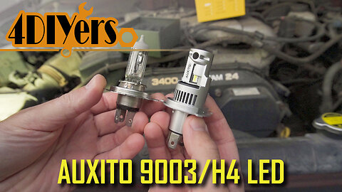
Review: AUXITO H4:9003 LED Headlight Bulbs 100w
I’ll be reviewing these 9003 or also known as H4 LED bulb replacements from Auxito. I’ll be testing them out in a 2001 Toyota Tacoma. On the outside of the box, you’ll have some product specifications such as the operating voltage between 9-30 V, IP 67 rating, 6000 K color temperature, operating temperature between -40°F to 176°F, 50,000 operating hours and aluminum housing. They have a thinner frame profile making the light emitting radius much closer to a halogen bulb. This not only maximized output and performance but also provides a clean beam output. #auxito #auxitoled #ledlights #toyotatacoma
Product link: https://www.auxito.com/products/9003-led-bulb-h4-hb2-led-headlight-bulb-20000-lumen?ref=xR3VZnDW&variant=42135668752628
AUXITO's website: https://auxito.com/xR3VZnDW
15% coupe code: 4DIYERS
Website: http://4diyers.com
Patreon: https://www.patreon.com/4diyers
Facebook: https://www.facebook.com/4diyers
Twitter: https://twitter.com/4DIYers
Instagram: https://www.instagram.com/4diyers/
Tumblr: http://4diyers.tumblr.com
Pintrest: https://www.pinterest.com/4diyers/
The LED lights are finished in a silver aluminum construction. There are four diodes on the light, two for low beams and two for high beams. Also included in the construction is a cooling fan, you can see the blades exposed just below the diode along with vent holes in the side. On the rear you can see the three terminals which is a plug and play setup. No modifications are required to install these. While some LED replacement bulbs do have adjustments, this one is designed so there’s no need for it that, it’s simply installed and you’re ready to go.
These have a smart IC driver with a 100w rating making them work in most vehicles without any radio inference problems, can-bus ready and prevent the chance of error warning lights on your vehicle.
For installation, start by opening the hood of the truck. Grab onto the tab for the rubber grommet, and pull upward and back at the same time. This will allow you to disconnect from the rear of the light housing. Once you have a view of the bulb, the last step for the removal is unclipping that metal retainer. It’ll have a tang on the one side, push this in, then pull it up and rotate out. The bulb can then be removed. Also make note of its orientation.
Make sure your hands are clean so you’re not getting the new LED replacement dirty. Insert it into the housing in the correct position. Those three tags on the outside are different sizes so it only fits in one orientation. Clip in that metal retainer, this will hold the LED light in place. Before installing that rubber grommet you can give it a quick test. Install the rubber grommet, there will be text printed on it that says top. This faces up. Ensure that the rubber grommet is clipped into place, this keeps out any dirt and moisture in the lens. It also pushes around the outside of the LED assembly. Finally is plugging in the electrical connector for the light, again this only has one orientation.
I am using the stock housing for testing. I have been testing these for a little while and haven’t found any issues where oncoming motorists were flashing their lights. These bulbs are rated for 20,000 lm as a pair and have a 50,000 hour lifespan. They are extremely easy to install, and no modifications are required for your vehicle. They have a compact design, 12,000 RPM cooling fans, and a 90° turning thermal fluid which improves the lifespan of the lights by keeping them cool. The high beams and low beams are all one assembly here, so they are a direct plug and play. Overall I am extremely happy with these lights. Living out in the country, there can be quite a bit of hazards on the road at night. Especially with no street lights, these will maximize my visibility while driving down those dark country roads. they help with reducing eye fatigue when driving at night, will allow you to see road signs easily, and greatly improve visibility regardless if you are using the lower or high beams.
Thank you to all those who watch my videos and support my content. Don't forget to subscribe to my channel for future tutorial videos and like my video if you found it helpful. New videos are always being uploaded every week!
© 4DIYers 2013
All Rights Reserved
No part of this video or any of its contents may be reproduced, copied, modified or adapted, without the prior written consent of the author.
17
views
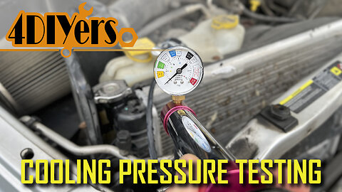
How to Pressure Test a Cooling System
How to pressure test your cooling system in your vehicle. This will help you determine if your system has a leak and potentially allow that leak to show up depending on its location. A leak in the cooling system will not only cause a loss of fluid but cause poor cooling performance too. Decreased pressure will also decrease the system’s boiling point. #oemtools #coolingsystem #autorepair
OEMTOOLS 27068 Pressure Testing: https://www.mobiledistributorsupply.com/27068-oemtools-universal-cooling-system-pressure-test-kit-oem
Website: http://4diyers.com
Patreon: https://www.patreon.com/4diyers
Facebook: https://www.facebook.com/4diyers
Twitter: https://twitter.com/4DIYers
Instagram: https://www.instagram.com/4diyers/
Tumblr: http://4diyers.tumblr.com
Pintrest: https://www.pinterest.com/4diyers/
Tools/Supplies Needed:
-pressure tester
Procedure:
For this, I’ll be using my OEMTOOLS 27068 universal cooling system pressure testing kit from Mobile Distributor Supply. This can work on most vehicles and can have extra attachments purchased to work on additional vehicles. It comes with everything you need all neatly packed in a blow mold case. This includes three expandable rubber adapters which provide a tight fit when tightened up in the radiator fill point or expansion today depending on your vehicle's cooling system design.
Simply screw on the rubber adapter to the flange attachment and this will then connect to the hand pump. There is a rotational lever on top which locks it down so it has a tight seal, this is for the removal and installation of the flange attachment.
Ensure your vehicle's cooling system is cold so we don’t risk the chance of burning yourself. Next is locating and removing your radiator cap. Here I am working on a 2006 Dodge Ram, this is one example.
As a second example, if you have a pressurized reservoir tank, then you would need to test the system here instead. This is on a 2010 BMW 335d. Again you’ll need to pick the appropriate insert, tighten it to ensure it doesn’t leak and then lock on the flange attachment. Pump the system up to the appropriate pressure rating and monitor the gauge. This particular cap doesn’t state the system pressure, however that information can be found online or in a repair manual.
Make sure the system is full of coolant or water if you will be repairing it right away. Air can compress more than water so it’ll take you longer to pressurize the system. With water in the system, you’ll also be able to spot the leak easier as the liquid will come out of the problem area instead of air.
The radiator cap will have the required system pounds, this is needed to be known for pumping up the system to the correct pressure measurement.
Next is installing the rubber adapter with one side of the flange. Once in place then tighten it up, The rubber will expand in the hole creating a tight fit allowing us to pressurize the system.
Connect the flange on the pump side, and flip the rotational latch to ensure it’s locked into place.
Using the hand pump, bring the system up to pressure which was listed on the radiator cap.
Then monitor the gauge for a pressure drop. If a leak is present, the pressure will drop and you may potentially hear or see liquid dripping.
Common areas to look for are rubber coolant hoses such as radiator or heater core hoses. It could be something as simple as a loose clamp. Other areas can include the water pump, thermostat housing, heated upper intakes, the side tanks on the radiator, around the head, frost plugs, heater core, etc. With a heater core, you may notice fluid inside the cabin of the vehicle around the footwell area or dripping from the duct drain. This could be something as complicated as a leaking head gasket or cracked block.
I would keep an eye on the gauge for about 10 minutes. If the pressure doesn’t drop over that period, then there is no leak. If a leak isn’t found, it could be in a hidden area such as a valley pan under an intake, a water jacket leaking through a head gasket inside the engine, etc. This will depend on the vehicle and how the engine is designed.
Once you have repaired the system, it’s always a good idea to re-test the system ensuring the problem has been repaired.
Thank you to all those who watch my videos and support my content. Don't forget to subscribe to my channel for future tutorial videos and like my video if you found it helpful. New videos are always being uploaded every week!
© 4DIYers 2013
All Rights Reserved
No part of this video or any of its contents may be reproduced, copied, modified or adapted, without the prior written consent of the author.
22
views

Review: Nilight 2006 2009 Dodge Ram Custom Black Headlights
Video review on these third generation Dodge Ram headlight housing upgrades from Nilight. This is a direct plug and play setup where you’re able to use your stock or upgraded bulbs, no modifications are required for your vehicle. This will fit a 2006 model which I have, however you will lose the function of the lower marker light in the factory house, however from 2007 to 2008, this is a direct replacement. For 2009, this will fit the 2500 and 3500 models of the same third generation body style. #nilight #dodgeram #dodgetrucks
Amazon headlight links:
USA: https://amzn.to/3zEUfyw
Canada: https://amzn.to/3P2eZWz
Nilight Website: https://www.nilight.com/
Website: http://4diyers.com
Patreon: https://www.patreon.com/4diyers
Facebook: https://www.facebook.com/4diyers
Twitter: https://twitter.com/4DIYers
Instagram: https://www.instagram.com/4diyers/
Tumblr: http://4diyers.tumblr.com
Pintrest: https://www.pinterest.com/4diyers/
So to give you an overview of the construction of the headlights. They use the same style of connectors for both the headlight bulbs and signal light bulbs. They come with new snap clips in the inner fenders, so if yours are missing or worn, they can be easily replaced. They have the same mounting brackets and adjustment screws. The front lens is clear, they have orange signal lights and Nilight has another version with clear signal lights too. The first impression is that they feel of good quality and appear to be well-made with a clean finish. It’s best to leave the plastic protectors on for the installation so they don’t become damaged.
The assemblies are almost identical with one difference being the parking light due to the one year availability option for 2006. These are a direct swap with no modifications required.
The interior assembly behind the lens is very similar, other than the black vs chrome finish and no lower parking light, the only other design difference is the side marker light. I have noticed it does have a cutout for the diffuser on the new replacements whereas the factory versions do not illuminate. These are very similar to a style Dodge offered on a specific model where not many were available. This was referred to as a Dodge Ram Nightrunner. The lack of chrome does not affect the performance of the lights, this is simply a trim feature.
They fit great in the fenders, your lights will most likely require adjusting like mine did and this will also adjust the gaps along the fender’s edge. Adjustment is very straight forward and this was covered in my previous video.
Here is a comparison between the stock and newly upgraded lights. As your factory lights age, the lenses will become foggy which is very common. This not only looks bad but also affects the light output. Chrome reflectors can also break down, also leading to poor performance of the lights, this then would lead to possible reasoning for changing your lights. These have an IP65 rating, meaning it has protection from low pressure water jets from any direction and full protection from any duct or other particles.
Headlights are DOT and SAE compliant ensuring they’re safe for your and fellow motorists on the road.
Lighting performance is better compared to the stock hazy lights. I am still using the stock bulbs, however, the beams do seem to be slightly more concentrated than compared to the factory versions. The beam on the new lights seems to travel future which is great for country road driving, this will allow me to see obstacles and animals quicker.
So far I’ve been using these lights for about 3 months and am extremely happy with the look and constriction. I haven’t noticed any issues with leaking water or condensation, they have maintained their adjustments and seem to hold up well to any road debris. I especially like the quality and styling, they provide an OEM look without the high OEM costs. I’ve had a fair amount of night driving and they seem to perform excellently so far. It is very important to aim these correctly so you’re getting the full performance out of these headlights.
Thank you to all those who watch my videos and support my content. Don't forget to subscribe to my channel for future tutorial videos and like my video if you found it helpful. New videos are always being uploaded every week!
© 4DIYers 2013
All Rights Reserved
No part of this video or any of its contents may be reproduced, copied, modified or adapted, without the prior written consent of the author.
2
views
How to Siphone Gas from a Boat Fuel Tank
How to siphon the fuel out in a boat. While I am using a boat as an example, this can be applied to other vehicles as well as long as there are no restrictions in the filler neck. The reason for extracting the fuel from the boat tank is that it does have some running issues which could be caused by stale fuel. The other reason is that I have done an oil injection delete, therefore I need to mix the fuel and oil. Having an empty tank and adding a new oil-fuel mixture will ensure I do have the proper ratio. #fueltank #autorepair #oemtools
Fluid Extractor: https://www.mobiledistributorsupply.com/24938-oemtools-24938-pneumatic-manual-fluid-extractor-2-5-gallon-9-5l-oem
Website: http://4diyers.com
Patreon: https://www.patreon.com/4diyers
Facebook: https://www.facebook.com/4diyers
Twitter: https://twitter.com/4DIYers
Instagram: https://www.instagram.com/4diyers/
Tumblr: http://4diyers.tumblr.com
Pintrest: https://www.pinterest.com/4diyers/
Tools/Supplies Needed:
-hose
-fluid extractor
Procedure:
Originally I had planned on removing one of the hoses going to the tank and then inserting a line. However some of the fittings were too small and the large filler hose was stuck in place. This is a plastic tank so I didn’t want to risk breaking off the hose fitting by forcing the hose loose.
Unfortunately the supplied hose wasn’t quite long enough, there is a larger distance between the fill location and the fuel tank at the bottom of the hull. Instead I used some clear rubber line that I had laying around. The supplied hose from the extraction pump was able to fit inside the extension hose I was using here. This hose fits into the filler neck location until it hits the bottom of the fuel tank. Rotating the hose while pushing it in place does help feed it down. It’s best to use a stiffer hose, anything softer will bind up inside the filler hose or neck.
Once everything is in place, pull up on the green handle and pump it down various times. This will create a vacuum and eventually the fuel will be safe and out of the tank. This is a great way for removing fuel as no electronics are involved which may cause a spark igniting any vapors, you do not have to remove the fuel tank with fuel in it as it can be heavy and awkward, and this will save time in repairs.
Any fuel which was removed will need to be disposed of appropriately and this can be dumped out the hose connection fitting.
Once all the fuel was removed after that was replenishing the fuel tank with the fresh fuel and oil mixture.
Thank you to all those who watch my videos and support my content. Don't forget to subscribe to my channel for future tutorial videos and like my video if you found it helpful. New videos are always being uploaded every week!
© 4DIYers 2013
All Rights Reserved
No part of this video or any of its contents may be reproduced, copied, modified or adapted, without the prior written consent of the author.
17
views
How to Make a Portable 12v Fuel Transfer Pump
How to make a fuel transfer pump. I have found some versions available online, however after reading the reviews, I didn’t want to be stuck with a poor product that quits after a couple of months of usage. I need the fuel transfer pump as I can no longer fill up with straight gas from the marine pumps for my boat, I am required to fill the tank with a gas and oil mixture as I did an oil injection delete. Also trying to fill the tank with a 20 liter or 5 gallon fuel can hanging over the edge of the boat isn’t the easiest task either. #oemtools #electronic #gasoline
Heat Gun: https://www.mobiledistributorsupply.com/24498-oemtools-24498-dual-temp-heat-gun-oem
Amazon affiliated links:
US:
Fuel pump: https://amzn.to/3WNW5rT
Brass sintered filters: https://amzn.to/3A202z5
Hose barb: https://amzn.to/3fXERaQ
Ear hose clamps: https://amzn.to/3DYYMxZ
Fuel hose: https://amzn.to/3WNXrTv
Switch: https://amzn.to/3NYyDnE
Canada:
Fuel pump: https://amzn.to/3Tte7wB
Brass sintered filters: https://amzn.to/3A4vEEg
Hose barb: https://amzn.to/3E0nI8e
Ear hose clamps: https://amzn.to/3WNXezH
Fuel hose: https://amzn.to/3TqZGcs
Switch: https://amzn.to/3NZ0rZ5
Website: http://4diyers.com
Patreon: https://www.patreon.com/4diyers
Facebook: https://www.facebook.com/4diyers
Twitter: https://twitter.com/4DIYers
Instagram: https://www.instagram.com/4diyers/
Tumblr: http://4diyers.tumblr.com
Pintrest: https://www.pinterest.com/4diyers/
Tools/Supplies Needed:
-soldering iron
-solder
-heat shrink
-heat gun
-wire cutters
-wire
-cigarette lighter plug
-fuel pump
-fuel hose
-fuel pump
-hose clamps
-brass sintered filter
-switch
Procedure:
First was stripping the wires on the fuel pump. The fuel pump only has two wires, the black is the ground and the brown is the power. The connector was cut off the cigarette lighter wire.
Both wires are the same color on the cigarette lighter, using a multimeter I was able to determine which is ground and which is the power wire. The center pin is the power and the outer contacts are the ground for the cigarette lighter plug.
Then was stripping these wires.
Heat shrink was then installed on both the ground and power wires. The wires are then twisted together and soldered. if you are looking for a tutorial on how to solder wires, I do have one for this.
Allow those soldered connections to cool before applying the heat shrink. Not doing so can have the heat shrink prematurely shrink around the connection making the installation difficult. After that is using a heat gun on the heat shrink.
For the switch installation, I had to separate the molded wire using a razor knife. Be extremely careful not to pierce the insulation on the wire as this may cause a short.
Using a screwdriver, the switch was disassembled. One wire will be routed inside the case and the other one will be routed to the switched portion. The power wire will need to be clipped so it does have a broken connection and the switch fully controls that part of the circuit.
I have found installing the wires on the opposite portion of the case is far easier than installing them on the wheel portion.
After that is putting the case back together and ensuring those wires are properly seated inside.
I also installed an extension of this wire so it was able to reach the cigarette lighter port in my cuddy cabin. Again the insulation was stripped back, the wires were soldered, and then heat shrink was applied.
The hose barb‘s fittings already have sealant applied to the threads.
Hose sizes may vary based on what type of fittings are included with the fuel pump.
A single ear clamp is used and that is crimped into place. Again the size of that clamp will vary based on the size of the hose.
This will be the suction line so a brass sintered filter is installed on the end with a hose barb. This also has a hose clamp applied.
The larger supply line is that installed. This will be a longer line as it needs to be able to reach the fuel tank filler area.
Once done, here is a quick test using the fuel can while being hooked up to the cigarette lighter in a vehicle.
And now for a test on the boat. As you can see I do have the wire running to the cuddy cabin, I can turn the pump on or off using that rotary switch, I have the suction line installed in the fuel tank with a filter so it doesn’t have the chance of picking up any debris and then the filler line is inserted into the gas cap for the boat.
Thank you to all those who watch my videos and support my content. Don't forget to subscribe to my channel for future tutorial videos and like my video if you found it helpful. New videos are always being uploaded every week!
© 4DIYers 2013
All Rights Reserved
No part of this video or any of its contents may be reproduced, copied, modified or adapted, without the prior written consent of the author.
66
views