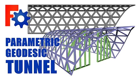
FreeCAD: Parametric Geodesic Tunnel
This model is available on Github, (I corrected the corners on the bottom plates)
https://github.com/Jeff-Tyndall/FreeCAD/blob/main/GEO-TUN-SS-16-T2-01.FCStd
This parametric model works well, recomputes fairly quickly, because it is very simple. The tunnel itself is made from one part, the triangular panel, and the panel is made of two features. And the whole assembly is driven by two sketches.
The sketches are all driven by the spreadsheet. This model is useful to determine the size of the tunnel and size of the panels themselves, to find good yield of materials. The vertical height of a panel is the length of one line segment of the big (18 side) polygon. The details and joinery of the panels can be created separately, so as to not to overly complicate the parametric model.
Made almost entirely in PartDesign Workbench, with the exception of the Arrays from the Draft Workbench, which is by far the best array in FreeCAD. When using the Array, (I find) it is best to accept whatever it says in the initial dialogue box, then correct the Array from its properties, so you can see the correct modelling.
This model can be created with different polygon shapes and different shape panels. The triangular panels can be right angle triangles, which would make any glass cutting much simpler. An 18 sided polygon works well because it makes a nice whole number of degrees. And has a peak on top and vertical sides at the bottom.
This could also be used to make a container or a lamp shade too.
When copying and pasting bodies, parts or assemblies, remember to deselect the spreadsheet, it should all be driven by the same spreadsheet.
Thanks for watching,
If you got anything out of it, hit the thumbs up.
5
views
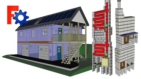
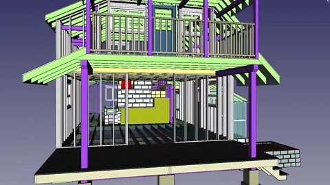
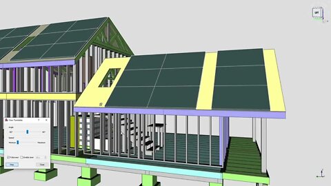
FreeCAD: Off-Grid Carriage House with Masonry stove
I like the idea of a large masonry heater in the center of the home. The stove is designed with concrete blocks, the flat slabs might have to be cast with steel wire mesh inside.
The model is made almost entirely with PartDesign WB. Only the rafters, stairs and deck have the structural design. It's far easier to model walls and floors as one part, but keeping the dimensions they would be constructed as. Structural design can be done when and if drawings are required.
The stove model is boolean fused and cut and chimney paths painted red. Clipping plane is good but doesn't display the cut face. But the boolean is it's own model and can be colored and turned on and off for clarity.
If you liked the video hit the thumbs ups.
Thanks for watching.
13
views
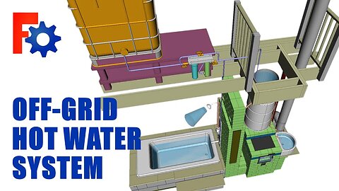
FreeCAD: Off-Grid hot water system
This design combines rain water collection and a rocket stove.
The stove has three circuits, controlled by the dampers:
1. A bypass (direct to chimney), to start the stove or or use just the stove.
2. The hot water tower with internal coil, for the shower and tub.
3. The tub ring to heat the tub, (all the internal voids could be filled with fiberglass or perlite).
The water plumbing has hot and cold to the shower mixer. The shower hot runs through tower coil. The sink hot runs direct from the 20 gal. pot.
For an outdoor hot tub, I think a thermosiphon (copper coil wrapped around a riser) would work great. But for a small indoor bit of plumbing, a gravity powered system might be best, it's always on and no lifting required.
If you like the video, don't forget to hit the thumbs up.
Thanks for watching.
31
views

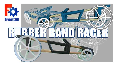
Rubber Band Racer and download
Rubber Band Racer. After making and breaking a couple of these, I wanted to make one which wouldn't break. And this led to being able to wind as much torque as possible into the car, the first thing to break will be the elastic. You can feel when the elastic band is reaching it's elastic limits.
The four 1/4" dowels are: 230mm long, and the 1/4" axle dowel is 80mm.
When assembling: test the dowel and hole fit and drill the pin holes after you've fit the axle, hook, and rear wheels together, that way the part acts as the drill jig. The rest is friction fit.
Try to set the tail hook as centered and perpendicular to the axle as possible, this will help the car run straight.
The download STL's are slightly different from the CAD recording, the front end is 2 parts now. Also with STL's is the native FreeCAD file (.FCstd) if you'd like to modify the model.
It goes pretty good, that's about 28' in the video, I think it could go 40 or 50'.
If you liked the video, hit the thumbs up.
Thanks for watching.
#FreeCAD #rubberbandcar #download
21
views
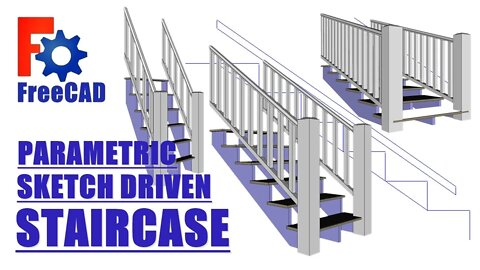
FreeCAD: Parametric sketch driven Staircase
Mostly parametric, less the number of steps, still thinking about that.
The driving sketch:
1. Contains only essential geometry and datum points.
2. When dragging sketches out their bodies, only link essential geometry with external geometry command. Create the rest of the sketches inside the body.
3. After the drive sketch is complete and bodies attached to it, it CANNOT be changed. The naming problem will cause things to jump around.
4. Constrain sketches in a way in which the constraint cannot flip over, using center points usually fixes that.
5. A stair sketch can be driven by overall height and run, or rise & run of each step.
6. Sketch geometry from another body can also be referenced by CarbonCopy + Ctrl, but that command converts the entire sketch, but would be possible to use by changing some lines to construction lines.
Stair design for a CAD model:
1. The Run: Start with run that is 1" -1.5" (nose and possible riser) less than the most common tread (11.5" in the US, 10.5" in Canada, deck boards are 5.5" x 2 + 1/8" = 11.125")
2. The Rise and number of steps: Divide the total height (finished floor to finished floor) by a number that results in a step rise of 7-8", it's better to land on an 1/16" or more.
3. Remember the first step of the cut stringer is 1 tread thickness less than the rest of the of the cut steps.
4.The railing: spindles no more than 4" apart, 2 spindles per step (no bottom rail ) works with certain geometry. Don't make railing sections to long, and small supports under sections is a good idea.
If you liked the video hit the thumbs up.
Thanks for watching.
28
views
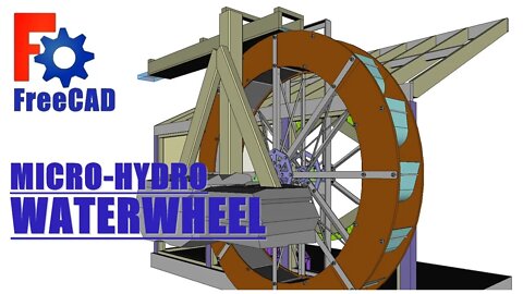
FreeCAD: Micro-Hydro Waterwheel
If you have 8'-12' head of water, a waterwheel maybe a good source of electricity. Small turbines will always be more efficient and be able to take greater advantage of the available energy resource.
But a well made waterwheel may have some advantages:
1. Aesthetics, there is a timelessness to the waterwheel.
2. Durability and ease of operation (vs the turbine).
This model is 8' diameter, and I imagine a flow of 5 gal/sec (0.02m3/s). Which produces 235 watts at 50% efficiency (from the Online Hydro Power Calculator). Not much, so gaining every bit of efficiency is important. The big pulley is to get the big jump in speed, then a second stage. A gearbox would be more efficient, but there is no flexibility to it, and in a possibly remote location basic is better.
The wheel I imagine being made of eight 12" bent composite deck boards sections cnc routed, same as the 6 sections of the big pulley. 3/16x2x1.5 angles, 5/16" plasma cut plate hub with weld-in bushing. The bucket backs are composite, the bucket fronts are light gage 12" aluminum, pushed into the slots.
The big pulley is fabricated the same way the wheel is. But the groove sections I think could be 3D printed and a twist-lock v-belt.
The shaft and all the hardware should be stainless. The big bearings? it turns so slow, a hardwood or solid bearing might be best (there goes the efficiency), it needs careful consideration (and a cover too).
I hope you enjoyed the video, thanks for watching.
956
views
1
comment
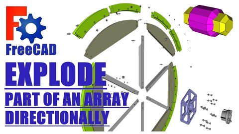
FreeCAD: Explode part of an array directionally.
It not always going to be the case where mating parts have mating planar faces. They maybe any shape, circular with this pulley. But the Create Simple Group command from the Exploded Assembly WB requires a planar face to project from. So.., we create a simple piece of geometry, which has faces to project normal from. And can turned off when creating drawings or an animation, just don't delete it.
Multiple reference objects could be created which stay with a sub-assemble and exploded out multiple times.
In this assembly I created a separate part for the exploded bodies which where copied (not cloned) and the originals turned off.
When using the Exploded Assembly WB: DO NOT deleted the ExploedAssembly folder or SimpleGroups when the assembly is exploded, the assembly or part will be left in the exploded position with no way home.
If you got anything out of it, hit the like button.
Thanks for watching.
1
view


Machine Elves Portal 01
Ever wonder what happens when you point a camera into the end of a Kaleidoscopic projector?
Not digitally created images.
4
views
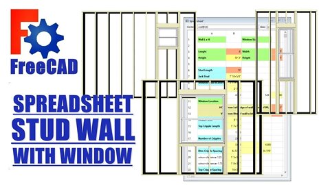
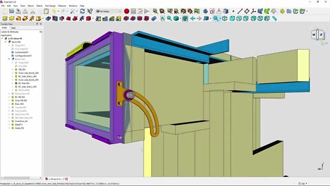
FreeCAD: Stud Wall with Window spreadsheet
Creating a parametric spreadsheet driven stud wall with window.
The Stud Wall with window assembly.
(I create this prior to inserting spreadsheet)
1. In PartDesign WB (or your choice), create bottom & top plates and one starter stud and one end stud. Create these bodies with the same origin and transform them into position.
2. From the Draft WB: use array command to create stud array. Ok anything in the dialogue box, and fix the array from the properties panel, with 16" spacing.
3.From the BIM WB: create a window. If the dialogue box doesn't create what you want, it can be fixed from the sketch.
4. Edit the window sketch: delete constraint off the origin point, drag sketch away from origin. Create a point on the center of the bottom line of the window sketch (symmetry command). Create a vertical and horizontal dimension from the origin to the point just created, these are the window location dimensions.
5. Hide any stud that touches the window. Copy and paste four studs and four bottom plates. Transform and re-dimensions these bodies into: 2 window studs, 2 jack studs, 2 headers and 2 sill plates. Create one top and bottom cripple. Always create bodies from the same assembly origin and transform into position. This is the rough window opening, it will all be located relative to the window location point.
We now have 2 datum points in this assembly. The assembly origin and the window location point. Everything in the assembly is located relative to one or both of these two points.
The Spreadsheet
1. From the Spreadsheet WB: create a new spreadsheet.
2. Name of all the bodies and dimensions that need to be controlled.
Wall LxH, Window LxH, Window location, stud length, stud spacing, sill width, header width, jack stud length, bottom & top cripple lengths, etc..
3. Of all the features controlled by the spreadsheet, only 6 are meant to be given entries/variables: Wall LxW, Window LxW and Window WxH.
4. Create and enter in all the equations to locate bodies: Wall H= stud length +3", sill W= window width + .25", etc...
5. Add all aliases to cells, keep names short, wall length: wl, window width: winw, window location vertical: winlv, etc...
6. Move through the assembly replacing dimensions with spreadsheet aliases (or equations) via the properties panel, click silver button. type sp in the dialogue box, hit down arrow, hit enter, type appropriate alias, hit enter, it will turn blue when link is created.
IMPORTANT: FreeCAD spreadsheet uses Python functions, NOT Excel. But some functions are the same.
Python function for rounding up is: ceil()
7. When creating number of studs and number of cripples. This number can NOT be a fraction or decimal. This is the trick of this assembly.
x number of studs = wall length / 16"
rounding up to make whole integer = ceil(x)
8. Creating the cripple arrays: The cripple spacing is different top and bottom because the header is 3" wider than the sill, so two arrays are required, but only one value changes in these two equations.
I know I blasted through this quickly, and skipped a lot and no dialogue. But this for intermediate to advanced people.
Cripple spacing: puzzled solved! (mathcodeprint ;-) )
If you got anything out of it, hit the thumbs up.
Cheers.
39
views
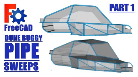
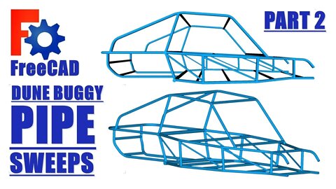
FreeCAD: Pipe Sweeps, Dune Buggy chassis, Part 2: Sweeps
FreeCAD Pipe Sweep is a powerful command. You can sweep just about anything. A sketch segment, multiple segments, the edge of a solid, the edge of a shape binder. You can sweep a profile on a path from another body inside another part.
The dragging and dropping of sketches out of then back into a body to use the reference geometry command (which only seems to work inside an assembly) works beautifully with sweeps. Often it requires just one coincident constraint at an origin point.
The use of solid body edges to sweep makes things much easier too. To change the shape of a solid is much easier than locating LCS's, planes and sketches, and making sure everything stays connected. This model would be a complicated, hard to understand, ready to explode mess, without building it on the solids shapes. Also, faces where you'd like shape binders for profiles to sit can be built into the solid frame.
When sweeping a multi segment sketch: select the profile sketch, then select the path sketch from the feature tree, not off the screen. It will sweep it all at once, as apposed to Add Edge, clicking on a segment, Add Edge, for every segment, when clicking the screen.
Thanks for watching,
If you got anything out of it hit the thumbs up.
20
views
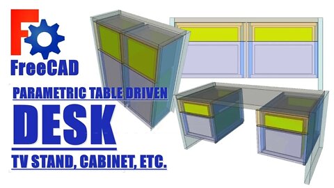
FreeCAD: Parametric Table Driven Desk, TV stand, cabinet,
Parametric Table Driven Desk, TV stand, cabinet. A 1000 different ways you could do this. One mistake I made is the sketch constraints on the lap cuts of the box, it kept flipping over, constraints worked that way too. And the depth extrudes should not have + - values, all should come off the spreadsheet, they would've messed up if I had changed the sheet thickness values. This is a design exercise on how I'd go about building a good model, not a tutorial on modelling.
I used at least one shapebinder. But better than shapebinders, I find, is dragging sketches out of their body into the part containing it. Then you can pick up any geometry needed from any other bodies in that part, with external geometry command. It's a powerful sketch technique, I highly recommend it.
5
views